


QUICKSTART GUIDE
Drive Configuration
7
Menu Settings
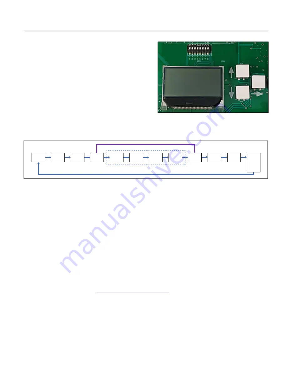
To adjust system settings, make sure power is off, and remove the
cover. Then, power the drive to make menu changes. When changes
are complete, power off the drive before replacing the cover.
Use the arrow keys to the right of the Display to navigate through the
setup menus.
•
The right arrow moves from screen to screen, and also functions
as an Enter key.
•
The up and down arrows scroll through the available options on
each screen.
•
When a selection has been made, you must press the Enter key
(right arrow) for the setting to take effect.
NOTE:
If DIP SW1 – Position 1 is
ON
, settings can be made either through the manual display, or through the mobile app. Changes in
either tool are reflected in the other. Power cycling the drive is not required for menu based or DIP switch settings to take effect.
Menu Navigation
Home Screen:
In normal operation, this screen displays the current system status. During setup, pressing the Enter key (right
arrow) changes the display to the
Motor Type
screen.
Motor Type:
Configures the drive for the type of motor being used. Selecting SUB configures the drive for use with a submersible
motor. Selecting CEN configures the drive for an above-ground, centrifugal motor.
NOTE:
SUB drive models can be configured for either type. CEN drive models can only be configured for CEN pump/motor type.
Max Amps:
The Max Amps value is used to configure various protection features (pump underload, motor overload, etc.). This
value should match the Service Factor Amps or Maximum Amps rating listed on the motor nameplate.
Sensor Type:
Configures the drive for the type of pressure transducer or sensor being used. Selecting
Transducer
displays the
Sensor
Range
screen. If a standard
Pressure Sensor
is selected, the target pressure is set using the adjusting screw on the sensor itself. The
Sys
-
tem Response
screen is displayed next for Pressure Sensor use.
Sensor Range:
This is only configurable when the sensor type is transducer. This setting scales system operation to the installed
transducer. The range is 100 to 300, with a default setting of
200 PSI
. When changing, the setting changes in 10 PSI increments.
Setpoints:
Drive speed control is based on the difference between the setpoint and the transducer feedback value. As user
demand (flow) causes pressure changes, the drive varies the output frequency (motor speed) to maintain pressure at or near the
target setpoint. There are two user configurable setpoints in the system—Setpoint 1 and Setpoint 2.
If an application has different
pressure requirements for specific uses, the dual setpoint feature can be used by connecting a switch to the
Dual Setpoint
terminal
block on the control board. Refer to
“Control Circuit Connections” on page 5
. When the dual setpoint input is open, Setpoint 1 is
used for pressure control. When the input is closed, Setpoint 2 is used.
•
Setpoint 1:
When using a Pressure Transducer, use this screen to set the desired target pressure the system will maintain
during normal operation. Recommended maximum value is 5% less than sensor max for proper operation.
•
Setpoint 2:
Set an alternate setpoint here.
NOTE:
Factory defaults for the Setpoints are 0 PSI. This puts the drive in the Sleep/Stop state, keeping the drive from running while
programming takes place. The Drive will run 5 seconds after SETPOINT 1 is adjusted above 0 PSI and NEXT button is pressed.
IMPORTANT:
Monitor pressure gauge during initial startup to ensure system does not over-pressurize.
Home
Motor
Type
Max Amps
Sensor
Type
Sensor
Range
Setpoint 1
Setpoint 2
Drawdown
System
Response
Underload
Sensitivity
Underload
Off Time
Submersible
Centrifugal
Transducer
Pres. Sensor
Pressure Sensor Only
Transducer Only
QR Code
Press
Down
button to
view Fault
Logs 1-5


