Franklin Electric MonoDrive Installation Manual Download Page 40

40

SubDrive/MonoDrive

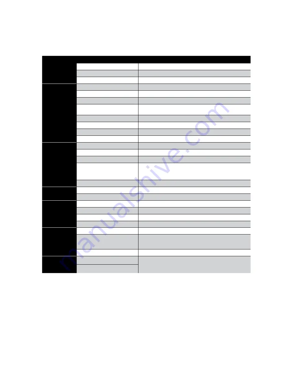
Specifications - SubDrive2W

SubDrive2W

Model No.

NEMA 1 (indoor)

Not Available

NEMA 3R (indoor/outdoor)

Model 5870203223

NEMA 4 (outdoor)

Not Available

Input from 
Power Source

Voltage

207-260 VAC

Phase In

Single-Phase

Frequency

60/50 Hz

Current (max)

14 Amps (RMS)  
(For circuit breaker sizing)

Power Factor

0.7 (approximate)

Power (idle)

20 Watts

Power (max)

1900 Watts

Wire Gauge Size(s)

Consult Federal, State, and Local codes for branch circuits installations

Output to Motor

Voltage

Adjusts with Frequency

Phase Out

Single-Phase (2-wire)

Frequency Range

30-60 Hz

Current (max)

6 Amps (RMS) 1/2 hp, 0.37 kW system

8 Amps (RMS) 3/4 hp, 0.55 kW system

10.4 Amps (RMS) 1 hp, 0.75 kW system

Wire Gauge Size(s)

NEMA 3R #6 - #18 * ga.

Pressure 
Setting

Factory preset

50 psi (3.4 bar)

Adjustment Range

25-80 psi (1.7 - 5.5 bar)

Operating 
Conditions

(A)

Temperature (at 230 VAC input)

-13 °F to 125 °F (-25 °C to 50 °C)

Relative Humidity (NEMA 1)

Not Available

Relative Humidity (NEMA 3R)

10-95%, non-condensing

Relative Humidity (NEMA 4)

Not Available

Controller Size

(B)


(approximate)

NEMA 1 (indoor)

Not Available

NEMA 3R

12 1/4” x 16 1/2” x 9”  
(31.1 x 41.9 x 22.9 cm)                                                                            
15.0 lbs (6.80 kg)

NEMA 4 (outdoor)

Not Available

For Use With

(C)

Pump (60 Hz)

1/2 hp pump/motor with 244505 - series 

3/4 hp pump/motor with 244507 - series [default]

1 hp pump/motor with 244508 - series

FE Motor Rating

Notes: 
 

(A) Operating temperature is specified at full output power when installed as described in Controller Location Selection on pg. 22.


(B) Refer to pg. 43 for detailed Mounting Dimensions.


(C) If a pump other than the default rating is used, refer to pg. 13 for Drive Configuration.


* Refer to pg. 28 for detailed Circuit Breaker and Wire Sizing. 


Summary of Contents for MonoDrive

Page 1: ...SubDrive75 100 150 300 2W MonoDrive MonoDriveXT Status État Estado Constant Pressure Controller Installation Manual ...

Page 2: ...use motor in swimming areas Before Getting Started s ATTENTION This equipment should be installed by technically qualified personnel Failure to install it in compliance with national and local electrical codes and within Franklin Electric recommendations may result in electrical shock or fire hazard unsatisfactory performance or equipment failure Installation information is available through pump ...

Page 3: ...ocedure 30 Wiring Connections 31 33 Special Instructions for Outdoor Installation 34 Strain Relief Installation Guide 35 Start Up and Operation 36 Specifications MonoDrive 37 MonoDriveXT 37 SubDrive75 38 SubDrive100 38 SubDrive150 39 SubDrive300 39 SubDrive2W 40 Mounting Dimensions 41 43 Accessories 44 Diagnostic Fault Codes Back Cover System Troubleshooting Guide Back Cover Tables 1 SubDrive and ...

Page 4: ...14 507 xxxx 3 4 hp 0 55 kW 5870203114 NEMA 4 214 508 xxxx 1 0 hp 0 75 kW MonoDriveXT 5870204110 NEMA 1 224 300 xxxx 1 5 hp 1 1 kW 5870204114 NEMA 4 224 301 xxxx 2 0 hp 1 5 kW Table 1 SubDrive and MonoDrive Models Declaration of Conformity Franklin Electric declares under our sole responsibility all SubDrive MonoDrive series 587 020 3xx0 controllers are in conformity with the Council Directives on ...

Page 5: ...llows installation in small spaces SubDrive MonoDrive Key Features Constant water pressure with a wide range of settings 25 80 psi 1 7 5 4 bar Smaller pressure tank can be used Fits the pump to the application pump speed is controlled to provide the optimum performance without overloading the motor Flexibility this unit can be used with standard off the shelf pumps No in rush power on transient cu...

Page 6: ... C D G F B A Controller Unit B Pot Adjustment Screw Driver C Pressure Sensor and Boot D Sensor Adjustment Tool E Sensor Cable F Installation Guide G Access Cover A Controller Unit B Pot Adjustment Screw Driver C Pressure Sensor and Boot D Sensor Adjustment Tool E Sensor Cable F Installation Guide G Strain Relief Fittings H Pressure Shut off Switch and Boot SubDrive75 100 150 300 MonoDrive MonoDriv...

Page 7: ...ced electronics to drive a standard motor and pump according to the pressure demands indicated by a highly accurate heavy duty long life pressure sensor By adjusting the motor pump speed the SubDrive MonoDrive can deliver constant pressure dependably even as water demand changes For example a small demand on the system such as a bathroom faucet results in the motor pump running at a relatively low...

Page 8: ... motor In addition SubDrives can spin a smaller pump slightly faster to boost output to roughly double its 60 Hz horsepower rating This allows use of smaller pumps for less system cost If a smaller pump of the desired flow rating is not available the controller can be configured to use larger pumps up to the horsepower rating of the motor SubDrive2W controllers are ideal for retrofit applications ...

Page 9: ...size a DIP switch must be positioned to select the correct pump rating Otherwise the SubDrive75 may trigger erroneous faults To configure the SubDrive75 for a 1 0 hp 0 75 kW or 1 5 hp 1 1 kW pump locate the DIP switch marked SW1 Use a small screwdriver provided to change the DIP switch setting according to the chart as shown s WARNING Serious or fatal electrical shock may result from contact with ...

Page 10: ... size a DIP switch must be positioned to select the correct pump rating Otherwise the SubDrive100 may trigger erroneous faults To configure the SubDrive100 for a 1 5 hp 1 1 kW or 2 0 hp 1 5 kW pump locate the DIP switch marked SW1 Use a small screwdriver provided to change the DIP switch setting according to the chart as shown Total Head ft Flow GPM 600 500 400 300 200 100 0 10 20 30 40 1 0 hp 0 7...

Page 11: ... be operated with a 3 0 hp 2 2 kW motor To operate a different pump size a DIP switch must be positioned to select the correct pump rating Otherwise the SubDrive150 may trigger erroneous faults To configure the SubDrive150 for a 2 0 hp 1 5 kW or 3 0 hp 2 2 kW pump locate the DIP switch marked SW1 Use a small screwdriver provided to change the DIP switch setting according to the chart as shown NEMA...

Page 12: ...kW curve and may only be operated with a 5 0 hp 3 7 kW motor To operate a different pump size a DIP switch must be positioned to select the correct pump rating Otherwise the SubDrive300 may trigger erroneous faults To configure the SubDrive300 for a 5 0 hp 3 7 kW pump locate the DIP switch marked SW1 at the lower right corner of the main circuit board Use a small screwdriver provided to change the...

Page 13: ...aging components Drive Configuration By default the SubDrive2W is configured at the factory to run a 3 4 hp 0 55 kW system To operate a 1 2 hp 0 37 kW or 1 0 hp 0 75 kW system a DIP switch must be re configured to select the proper system rating Failure to match the configuration to the rating of the pump and motor may trigger erroneous faults To configure the SubDrive2W for a 1 2 hp 0 37 kW or 1 ...

Page 14: ...rect the problem or extend the life of aging components Drive Configuration By default the MonoDrive is configured at the factory to run a 3 4 hp 0 55 kW system To operate a 1 2 hp 0 37 kW or 1 0 hp 0 75 kW system a DIP switch must be re configured to select the proper system rating Failure to match the configuration to the rating of the pump and motor may trigger erroneous faults To configure the...

Page 15: ...fe of aging components Drive Configuration By default the MonoDriveXT is configured at the factory to run a 1 5 hp 1 1 kW system To operate a 2 0 hp 1 5 kW system a DIP switch must be reconfigured to select the proper system rating Failure to match the configuration to the rating of the pump and motor may trigger erroneous faults To configure the MonoDriveXT for a 2 0 hp 1 5 kW system locate the D...

Page 16: ...it becomes necessary to desensitize the Underload trip level remove power and allow the controller to discharge Once the internal voltages have dissipated locate the DIP switch marked SW1 at the lower right corner of the main circuit board Use a small screwdriver provided to change Position 3 to the ON position to select the lower Underload sensitivity as shown in the chart below NEMA 1 s WARNING ...

Page 17: ...lls then the Underload Potentiometer Pot will need to be adjusted to a lower sensitivity setting Using a non conductive i e plastic pot adjustment tool adjust the pot located just to the right of the sensor connection counterclockwise Check the Underload trip level and repeat as necessary In cases where the pump is set very deep run the system at open discharge to pump the well down and observe ca...

Page 18: ...an well and the system continues to trip even with Position 3 of the DIP switch set to the ON position for Low shallow wells then the Underload Potentiometer Pot will need to be adjusted to a lower sensitivity setting Using a non conductive i e plastic pot adjustment tool adjust the pot located just to the right of the sensor connection counterclockwise Check the Underload trip level and repeat as...

Page 19: ...educe the controller s reaction time to sudden changes in flow If it is necessary to adjust the pressure control remove power and allow the controller to discharge Wait 5 minutes to allow internal voltage to dissipate locate the DIP switch marked SW1 Use a small screwdriver provided to move position 4 to ON as shown s WARNING Serious or fatal electrical shock may result from contact with internal ...

Page 20: ...ait 30 seconds to 5 minutes determined by duration of the previous run time before restarting the motor For example the first time the fault occurs the controller will wait 30 seconds before attempting to restart the pump If the system would then run for 1 minute and an Underload fault recurs the controller will wait 4 minutes before attempting to restart the pump This schedule allows for the mini...

Page 21: ...OR SHUT OFF INT FAN INV FAN PFC FAN NC NO COM RELAY SW2 SW1 O N Relay Connection NC NO COM RELAY BLK BLK OUTPUT GND L1 L2 GND INPUT PRESSURE SENSOR NC NO COM 1 Run Mode Mode d execution Modo en funcionamiento SW1 DISPLAY VITRINE ESCAPARATE SATUS ÉTAT ESTADO 2 3 4 5 6 7 Idle Mode Mode veille Modo inactivo Sleep Mode Mode sommeil Modo suspendido Motor Underloaded Sous charge de moteur Motor con poca...

Page 22: ...ve at one junction If a tank tee is not used the pressure sensor should be located within 6 feet 1 8 meters of the pressure tank to minimize pressure fluctuations There should be no elbows between the tank and pressure sensor 2 The unit should be mounted on a sturdy supporting structure such as a wall or supporting post Please take into account the weight of the unit 3 The electronics inside the S...

Page 23: ...reaker Wiring To Motor Pressure Sensor Wiring Power Supply From Circuit Breaker Wiring To Motor Pressure Sensor Wiring CORRECT INCORRECT s CAUTION There should be at least 6 inches of clearance on each side and below the SubDrive MonoDrive unit to allow room for air flow Pressure Relief Valve Pressure Tank 6 min 6 min Clearance For Air Flow 6 Feet or Less Pressure Tank to PressureSensor Pressure S...

Page 24: ...recommended minimum tank size NEMA 1 SubDrive75 100 150 MonoDrive MonoDriveXT Controller Pressure Sensor Cable included Note To avoid possible interference with other appliances please refer to the Installation Guide and observe all precautions regarding power cable routing Submersible pumps can develop very high pressure in some situations Always install a pressure relief valve able to pass full ...

Page 25: ...urce L1 L2 Input Configuration Switch Output to Motor Red Yel Blk Brn Blue Blk Output included NEMA 4 SubDrive75 100 150 MonoDrive MonoDriveXT Controller Blk Red Sensor Connection PRESSURE SENSOR See Pump Sizing section under the appropriate controller model for proper configuration setting Note To avoid possible interference with other appliances please refer to the Installation Guide and observe...

Page 26: ...tion under the appropriate controller model for proper configuration setting Blk Red Grn Wh Sensor Connection PRESSURE SENSOR PRESSURE SHUT OFF From Power Source L1 L2 Input To Residence Discharge into drain rated for max pump output at relief pressure Pressure Sensor Cable included Motor Cable Note To avoid possible interference with other appliances please refer to the Installation Guide and obs...

Page 27: ...etting Motor Cable Power Supply from Circuit Breaker Mounting Screw Location Franklin Electric Motor Pump Discharge into drain rated for max pump output at relief pressure Pressure Gauge Pressure Sensor Pressure Relief Valve Drain Valve To Residence Tank Precharge Inflation Valve Pressure Tank See Table 4 on Page 29 for recommended minimum tank size NEMA 3R SubDrive2W Pressure Sensor Cable include...

Page 28: ... MonoDrive 15 208 80 125 205 315 500 790 980 1290 1635 15 230 95 150 250 385 615 970 1200 1580 2000 SubDrive75 15 208 70 110 185 280 450 710 880 1160 1465 15 230 85 135 225 345 550 865 1075 1415 1795 SubDrive2W 20 230 125 205 315 505 795 985 1295 1645 MonoDriveXT 20 208 85 140 220 345 550 680 895 1135 20 230 105 175 265 425 670 835 1095 1390 SubDrive100 25 208 115 180 285 450 555 730 925 20 230 85...

Page 29: ...0 or MonoDriveXT 8 gallons 30 3 liters SubDrive300 20 gallons 75 7 liters All flows SubDrive2W 20 gallons 75 7 liters The minimum supply pipe diameter should be selected not to exceed a maximum velocity of 8 ft sec 2 4 m s See Table 6 below for minimum pipe diameter The pressure tank pre charge setting should be 70 of the system pressure sensor setting as indicated in the following table Table 4 M...

Page 30: ...serted to secure the unit from ever sliding up 5 If the mounting surface is a 4 10 cm 4 10 cm wooden post for the NEMA 4 models use the top center and bottom center mounting holes 6 Remove the SubDrive lid as shown in Figure 2 below NEMA 1 SubDrive75 100 150 MonoDrive MonoDriveXT Lid Screws Quantity 2 Required For Shipping May Be Discarded If Desired Mounting Screw Locations User Supplied Quantity...

Page 31: ...ng wire no smaller than motor cable wires To reduce risk of electrical shock disconnect power before working on or around the water system Do not use motor in swimming areas NEMA 4 SubDrive75 100 150 MonoDrive MonoDriveXT Figure 3 Motor Lead Connections Output to Motor Red Yel Blk Output BLACK RED RED YEL BLK BRN E4 BLU GND OUTPUT E3 RV2 E5 E1 E2 E6 TO L1 L2 INPUT RED YEL INPUT FILTER TO OUTPUT FI...

Page 32: ...le to use similar 22 AWG wire for distances up to 100 feet 30 m from the pressure sensor A 100 foot 30 m section of pressure sensor cable is available from your local Franklin Electric distributor See Accessories section for details pg 44 8 Verify that the SubDrive MonoDrive unit is properly configured for the horsepower rating of the motor and pump being used See the section on Pump Sizing for in...

Page 33: ...e adjustment range is between 25 and 80 psi 1 7 and 5 5 bar 1 4 turn approximately 3 psi 0 2 bar c Replace the rubber end cap d Cover the pressure sensor terminals with the rubber boot not to be placed in direct sunlight provided Figure 5A 13 Applies to SubDrive300 only Connect the sensor end of the pressure sensor cable with the two 1 4 quick connect terminals to the pressure shut off switch The ...

Page 34: ...l installation procedures Installation Procedures for NEMA 4 To assure maximum weather protection the unit must be mounted vertically with the cover properly aligned and secured as described below Use appropriate weather tight conduit fittings to maintain NEMA 4 rating When replacing the cover tighten all cover screws for maximum weather resistance Tighten Cover Screws Here Tighten Cover Screws He...

Page 35: ...osure SubDrive75 100 150 and MonoDrive XT Carefully punch out the outermost knockout hole on the bottom side of the drive See FIGURE 8 below Install the strain relief body and locking nut as shown in FIGURE 9 below Feed the pressure sensor cable through the sealing nut and then through the strain relief body Connect the pressure sensor quick connects to the drive circuit board prior to tightening ...

Page 36: ...s the speed of the pump several psi above the set point and shuts off the pump This adds some time to bleed off before the system starts up again NOTE Conventional private water systems intermittently fill a pressure tank as commanded by a standard pressure switch e g 30 50 psi 2 07 3 4 bar The SubDrive MonoDrive maintains a constant pressure at the pressure sensor up to the maximum capability of ...

Page 37: ...ain Phase 13 2 Amps RMS 2 hp 1 5 kW system Wire Gauge Size s NEMA 1 10 16 ga NEMA 4 6 18 ga NEMA 1 6 18 ga NEMA 4 6 18 ga Pressure Setting Factory Preset 50 psi 3 4 bar 50 psi 3 4 bar Adjustment Range 25 80 psi 1 7 5 5 bar 25 80 psi 1 7 5 5 bar Operating Conditions A Temperature at 230 VAC input 13 F to 125 F 25 C to 50 C 13 F to 125 F 25 C to 50 C Relative Humidity NEMA 1 10 95 non condensing 10 ...

Page 38: ...re Setting Factory Preset 50 psi 3 4 bar 50 psi 3 4 bar Adjustment Range 25 80 psi 1 7 and 5 5 bar 25 80 psi 1 7 5 5 bar Operating Conditions A Temperature at 230 VAC input 13 F to 125 F 25 C to 50 C 13 F to 125 F 25 C to 50 C Relative Humidity NEMA 1 10 95 non condensing 10 95 non condensing Relative Humidity NEMA 3R Not Available Not Available Relative Humidity NEMA 4 0 100 condensing 0 100 cond...

Page 39: ...MA 4 2 18 ga Pressure Setting Factory Preset 50 psi 3 4 bar 50 psi 3 4 bar Adjustment Range 25 80 psi 1 7 5 5 bar 25 80 psi 1 7 5 5 bar Operating Conditions A Temperature at 230 VAC input 13 F to 125 F 25 C to 50 C 13 F to 125 F 25 C to 50 C Relative Humidity NEMA 1 10 95 non condensing N A Relative Humidity NEMA 3R Not Available Not Available Relative Humidity NEMA 4 0 100 condensing 0 100 conden...

Page 40: ...ting Factory preset 50 psi 3 4 bar Adjustment Range 25 80 psi 1 7 5 5 bar Operating Conditions A Temperature at 230 VAC input 13 F to 125 F 25 C to 50 C Relative Humidity NEMA 1 Not Available Relative Humidity NEMA 3R 10 95 non condensing Relative Humidity NEMA 4 Not Available Controller Size B approximate NEMA 1 indoor Not Available NEMA 3R 12 1 4 x 16 1 2 x 9 31 1 x 41 9 x 22 9 cm 15 0 lbs 6 80 ...

Page 41: ...entimeters approximate Dimensions in Inches and Centimeters approximate NEMA 4 A B C D E F G H I Dimension 7 25 18 42 12 6 32 7 0 17 78 13 6 34 54 12 5 31 75 14 8 37 59 0 875 1 100 closed 1 100 2 79 1 375 3 49 0 473 1 20 0 875 2 22 Conduit Sizes 1 27 1 91 1 91 1 2 59 1 27 NEMA 1 A B C D E F G H Dimension 5 25 13 34 11 5 29 21 5 5 13 97 9 75 24 77 12 8 32 51 14 0 35 56 1 12 2 85 0 5 1 27 Conduit Si...

Page 42: ...imensions in Inches and Centimeters approximate SubDrive300 Outdoor Enclosure NEMA 4 NEMA 4 A B C D E F G H I J Dimension 8 75 22 23 12 00 30 48 6 0 15 24 15 34 38 96 14 00 35 56 14 75 37 47 1 37 3 48 0 885 2 25 1 71 4 34 4 75 12 07 Conduit Size 1 2 54 1 27 1 3 18 ...

Page 43: ...nd Centimeters approximate SubDrive2W Outdoor Enclosure NEMA 3R NEMA 3R A B C D E F G H Dimension 9 91 25 17 14 27 36 25 6 2 15 74 5 25 13 33 5 5 13 97 11 87 30 15 0 44 1 12 0 88 1 13 Conduit Size 1 2 3 4 C D A B Status État Estado F E G Use knock outs as required H ...

Page 44: ...ternal Cooling Fan Replacement Kit Replacement External fan SD75 and MD 225 635 901 NEMA 4 External Cooling Fan Replacement Kit Replacement External fan SD100 SD150 and MDXT 225 635 902 NEMA 4 External Cooling Fan Replacement Kit Replacement External fan includes two fans SD300 225 635 903 NEMA 4 Internal Stirring Fan Replacement Kit Replacement Internal Stirring fan SD75 SD100 SD150 SD300 MD MDXT...

Page 45: ...SubDrive MonoDrive 45 Notes ...

Page 46: ...46 SubDrive MonoDrive Notes ...

Page 47: ...gnment Dragging motor and or pump Abrasives in pump Amperage above SFL at 10 Hz Remove and repair or replace as required 4 MonoDrive MonoDriveXT only INCORRECTLY WIRED MonoDrive only Wrong resistance values on main and start Wrong resistance on DC test at start Check wiring check motor size and DIP switch setting adjust or repair as needed 5 OPEN CIRCUIT Loose connection Defective motor or drop ca...

Page 48: ...connect power and check pressure gauge for pressure drop Set deeper in the well or tank install a flow sleeve with airtight seal around drop pipe and cable If fluctuation is only on branches before sensor flip DIP switch 4 to on 07C and newer RUN ON WON T SHUT DOWN FLASHING GREEN Pressure sensor placement and setting Tank pre charge pressure Impeller damage Leaky system Sized improperly pump can t...

Reviews: