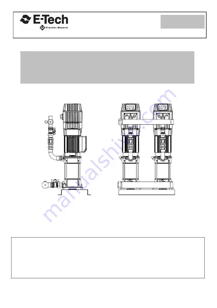
USE AND INSTALLATION MANUAL
BOOSTER SETS WITH VARIABLE SPEED
by frequency inverter for each pump
PR. T :
FG018572
Ed. 01 Rev. 00
Data: 01/04/19
Page 1: ...USE AND INSTALLATION MANUAL BOOSTER SETS WITH VARIABLE SPEED by frequency inverter for each pump PR T FG018572 Ed 01 Rev 00 Data 01 04 19 ...
Page 2: ...e 6 5 Working limits page 7 6 Installation page 8 7 Electric connections page 9 11 8 General features page 12 13 9 Run commissioning page 13 10 Hydraulic scheme page 14 11 Troubleshooting page 14 12 Dangerous areas page 15 16 13 Disposal of the product at the end of useful life page 17 TABLE OF CONTENTS ...
Page 3: ...LARATION OF CONFORMITY 2014 30 UE Regarding Electromagnetic Compatibility 2014 35 UE Relating to the electrical materials destined for use within particular voltage limits UNI EN 12100 2010 Safety of Machinery Basic concepts general principles of design Basic terminology methodology Technical principles and specifications CEI EN 60204 1 Safety of Machinery Electrical equipment of machines General ...
Page 4: ...igned to start automatically Make hydraulic connections and to prime the pumps before making any electrical connections WARNING The connection of the control panels must be performed by a qualified electrician in accordance with the present electrical standards WARNING The booster set and control panels must be connected to an efficient earthing system in accordance with the electrical standards o...
Page 5: ...e pump s speed rotation which is connected and maintain a fixed pressure at the setted flow rate variance Functioning The lowering of pressure in the system caused by withdrawal of water the pump is put in operation to meet the water flow required Each inverter DRIVE TECH also provides motor protection and monitoring such as protection against overload and dry running integrated soft start and sof...
Page 6: ...s in the installation or use can cause serious damage to the machine the user system and the people involved Do not make any action maintenance repairs or modifications that you do not have specific knowledge or received detailed instructions If doubts remain after consultation with the following paragraphs surveyed E Tech srl All operations must be carried out while respecting the safety rules Re...
Page 7: ...andard 35 C Maximum liquid temperature accepted by the materials 90 C 40 C for models with plastic impeller or other component in contact with the liquid Relative humidity max 50 at 40 C in the absence condensation CEI EN 60439 1 Air impurities the air must be clean CEI EN 60439 1 The presence of acid vapours corrosive gases uncommon amounts of dust are not permitted Altitude max 1000m above sea l...
Page 8: ...sassemble the rubber feet and fix the unit to the base using the relevant screws Vibrations must not occur during functioning The unit can only be installed in the horizontal position In the applications with positive suction head the suction pipe must not be smaller than that of the intake manifold In the applications with negative suction head in particular cases there may be the necessity to re...
Page 9: ...he power input of the inverter A A Connect the power cable of the inverter DRIVE TECH B motor output connection already connected For single phase power supply the voltage of the inverter DRIVE TECH supply line must be 230Vac and may vary in a range between 15 The power cord must be 3 wire 2 core earth the section of cable to be used for a line length of up to 30m must be at least 2 5 mm The conne...
Page 10: ... power supply single phase 230Vac to the power supply panel and connect the power supply panel to the inverter Turn on the circuit breaker After plugging in the power supply and switch the breaker operated press the START button to start the group Connect the power supply three phase 400Vac to the power supply panel and connect the power supply panel to the inverter Turn on the circuit breaker ...
Page 11: ...ree core cable with a minimum section 0 5mm2 exploiting the positions S S and G present in the control card if you use the DRIVE TECH 209 414 418 425 If the function COMBO is required with the DRIVE TECH 214 and the DRIVE TECH 409 the connection between the inverter DRIVE TECH is carried out using a bipolar cable connected to terminals 3 and 4 ...
Page 12: ...ther inverter DRIVE TECH to realize the combinated operation Special chokes optional allow the inverter DRIVE TECH to break down the dangerous overvoltages that occur in long cable runs and then make the inverter DRIVE TECH optimal control of pumps GENERAL TECHNICAL DATA Power supply voltage 230 Vac 15 single phase 380 460Vac 15 three phase Frequency 50 60 2 hz Protection level IP55 Maximum workin...
Page 13: ...mage to mechanical sealing and internal rotating couplings Priming must be performed before system start up Whenever the equipment is powered by the mains upon initial installation following voluntary shutdown or in the event of a power cut and the subsequent return of power it will enter a start phase lasting about few seconds Because all of the operating parameters including its alarm blocking c...
Page 14: ...hat the value at which the pressure switch is set to stop the motor is not higher than the pressure than the pump can generate suction delivery 2 Check that the pressure switch contacts move freely 1 Set the pressure switch at a lower pressure 2 Otherwise change the pressure switch The pressure transducer starting and stopping frequently during normal water delivery 1 Check the setting of the pres...
Page 15: ...lectrical Parts of private appropriate protections fixed electric shock high low Media Media Shielding of shares by the foam protection Formation and information service personnel through the user manual and maintenance and special labels Information on the need for maintenance with all power sources disconnected After maintenance before restarting the machine replace guards may be removed fig 2 p...
Page 16: ...LTAGE Fig 1 INVERTER DrivE Tech open REMOVING THE PROTECTION RISK OF ELECTRIC SHOCK ELECTRIC CURRENT Fig 2 Electropump terminal block AREA OF HANDLING AND INSTALLATION MOVING LOADS Fig 4 Heavy loads BOX FILTER NETWORK OPEN RISK OF ELECTRIC SHOK ELECTRIC VOLTAGE Fig 3 Filter box open only three phase versions ...
Page 17: ...n equivalent type of equipment for the purpose of starting the correct recycling disposal In Italy the domestic EEE are the electric pumps with single phase motor in other European countries it is necessary to verify this classification PROFESSIONAL AEE The separate collection of this equipment at the end of its life is organized and managed by the manufacturer The user who wants to get rid of thi...
Page 18: ...18 ...