


17
FRÄNKISCHE |
OI WLAN Access Point 100 DATALIGHT
®
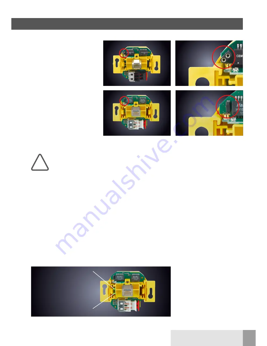
3.6.4 Meaning of the LEDs
For detailed error analysis and commis-
sioning, you can also use the state of
the green LEDs which can be seen with
the cover removed from the upper
component of the WLAN AP. They
show the activity on the respective
ports (UAE socket and POF connector).
With newer variants/versions of the
WLAN AP, there is an additional LED
at the RJ45 port for diagnostic / function
display available:
n
LED blue = WLAN
n
LED orange = LAN
n
LED purple = WLAN/LAN active
n
flashing = data traffic
Proceed as follows to
reset your WLAN AP to
factory settings if you no
longer have access to
your WLAN AP:
De-energize the WLAN AP!
n
The PC network card must be
in the same IP range!
n
Create a bridge at the device
(see 3.6.2).
n
Turn the power back on.
n
Wait 5 seconds. Go to, e.g., "Win-
dows - Start - Run" and enter “cmd”.
n
Confirm with “OK”.
n
Enter “tftp -i 192.168.1.1 put
acw-rk- xxxx.bin” (see meaning).
Meaning of the entries:
C:\
Change to the root directory
tftp
Start TFTP client (available
in the operating system)
-i
binary file transfer
192.168.1.1
Address of the TFTP
server in the WLAN
AP
put
Send data
acw-rk-xxxx.bin File name (xxxx is,
e.g., a version number
like 2000) must be in
the root
The system gives a feedback
regarding successful data transfer.
!
3 Configuration
3.6.3 Reset to factory settings / loading firmware in the event of a malfunction
POF connection
(fast flashing = no link,
slow flashing = link)
LED indicator status
3.6.2 Reset in the event of malfunction
Devices with multi-pin connector
socket:
Create a bridge (e.g., with a paper clip)
for a minimum of 5 and a maximum of
30 seconds during operation. The sys-
tem starts with the factory settings.
Devices with a reed contact:
Hold the reset magnet to the reed con-
tact for at least 5 and a maximum of 30
seconds during operation (see figure).
The system starts with the factory set-
tings.


