FRAKO Kondensatoren- und Anlagenbau www.frako.com
OPERATING MANUAL
The controller that maximizes reliability and monitors power quality
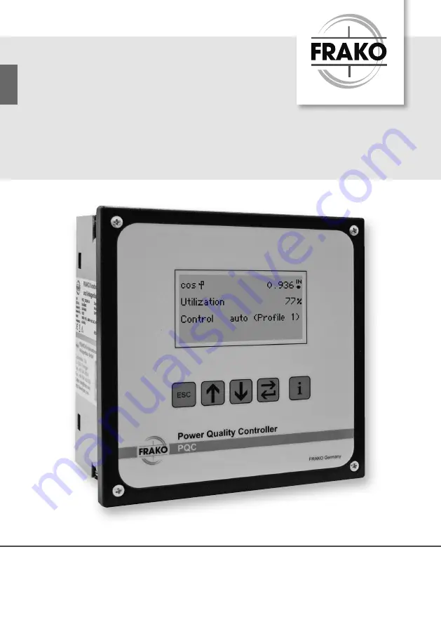
PQC
Power Quality Controller
Page 1: ...FRAKO Kondensatoren und Anlagenbau www frako com OPERATING MANUAL The controller that maximizes reliability and monitors power quality PQC Power Quality Controller ...
Page 2: ... 5 1 1 Preparing for installation 18 5 1 2 Scope of supply 18 5 1 3 Suitable location 18 5 1 4 Mounting the instrument 19 5 2 Electrical installation 20 5 2 1 Electrical installation procedure 20 5 2 2 Completing the electrical installation 21 5 2 3 Specifications for the electrical connections 22 5 2 4 Earth connection 22 5 2 5 Power supply 22 5 2 6 Voltage measurement 23 5 2 7 Current measuremen...
Page 3: ...3 3 Control parameters 46 6 3 4 Alarms 54 6 3 5 Communication optional 59 6 3 6 Temperature I O optional 62 6 3 7 Service 64 6 4 About PQC 66 6 5 Factory settings 66 6 6 Service interface 70 7 General operation 71 8 Cleaning and maintenance 72 8 1 Safety during cleaning and maintenance 72 8 2 Cleaning 72 8 3 Maintenance 72 9 Troubleshooting 73 10 Decommissioning and removal storage and disposal 77...
Page 4: ... be in accordance with this manual 1 2 Safekeeping This operating manual contains important instructions for operating the PQC safely correctly and cost effectively It is to be considered part of the instrument itself and must be held in a secure place where it can be referred to at all times 1 3 Symbols used in this manual Special instructions in this operating manual are marked by symbols and se...
Page 5: ...y CAUTION This key word indicates a hazard with a low level of risk that if not avoided can result in slight or moderate injury ATTENTION Damage to property could occur if this sign is not heeded Notes Notes supplement the general text with additional information on the correct func tioning and fault free operation of the PQC They are marked with the white on blue symbol on the left hand side as s...
Page 6: ...fe threat ening Installation commissioning and decommissioning of the PQC may only be carried out by appropriately qualified technicians who are also familiar with and under stand the contents of this manual When the PQC is being installed or serviced the instrument and the electrical system must be isolated from the power supply The isolated electrical system must be locked out and tagged to prev...
Page 7: ...cident Insurance Institution covering electrical installations In other countries the equivalent local regulations must be followed The safety of the system in which the PQC is incorporated is the responsibility of the persons installing and operating the system For safety reasons and to retain conformity with product approval requirements CE marking the user is not permitted to convert or otherwi...
Page 8: ... IEC EN VDE etc relevant to this product and the protection of persons and assets must be observed In Germany it is essential to comply with the Equipment Safety Act GSG and the regulations of the German Social Accident Insurance Institutions In other countries the equivalent local regulations must be followed 2 6 Repair Should repair work be necessary the customer or user must contact the manufac...
Page 9: ...V transformer In areas where UL CSA standards apply versions PQC xxx480x xx networks with nominal voltages 115 600 V AC power failure detection after duration of a half wave Current path measurement inputs x 5 A AC or x 1 A AC transformer secondary current 15 mA electri cally isolated power draw maximum 1 VA per transformer connection continuous overload rating up to 6 A AC transient overload maxi...
Page 10: ... System Outputs Category 12 output relays 6 output relays 6 output relays Type 120xxxx xx 060xxxx xx 061xxxx xx Output relays outputs for switching stages NO contact with common pole P AC 14 250 V AC maximum 3 A or DC 13 30 V DC maximum 3 A mechanical service life 2 107 cycles electrical service life AC 14 at 3 A 1 105 cycles AC 14 at 0 5 A 2 106 cycles AC 14 440 V AC max 3 A or DC 13 125 V DC max...
Page 11: ...ections Via pluggable screw terminals Type xxx240x xx xxx480x xx Instrument power AUX Insulation rating Conductor cross section max 2 5 mm min 0 2 mm min 250 V AC 70 C 500 V AC 70 C Protective earth PE Via 6 3 mm female slide connector conductor cross section at least equal to the largest conductor cross section of the AUX phases the voltage measurement connections the output relays and the alarm ...
Page 12: ...us Frakobus Conductor cross section max 1 5 mm min 0 14 mm Insulation rating 50 V DC 70 C Input for profile switching Conductor cross section max 1 5 mm min 0 14 mm Insulation rating 50 V DC 70 C Note 0 14 mm2 AWG 26 0 2 mm2 AWG 25 1 4 mm AWG 16 2 5 mm AWG 14 Design data Dimensions W x H x D 144 mm 144 mm 70 mm casing 144 mm 165 mm 70 mm casing including connectors Mounting Front of panel in 138 m...
Page 13: ...version can cause radio interference in resi dential areas In this case users may be called upon to take appropriate remedial measures at their own expense From hardware version V1 2 EN 55022A EMI 30 MHz 1 GHz office and residential area Class B EN 61000 4 6 immunity to conducted disturbances level 10 V RMS 150 kHz 80 MHz1 PQC xxxxxxx 3x EN 55022A EMI 30 MHz 1 GHz office and residential area Class...
Page 14: ...C to 65 C noncondensing Installation altitude Maximum height above sea level 2000 m Measuring system Accuracy Voltage and current measurement 1 at 50 60 Hz and 25 C ambient temperature Averaging function Over 1 second updated every 100 ms Harmonics Measured via Lx N All even and uneven harmonics up to the 19th ...
Page 15: ...in as required in order to restore the target power factor If the inductive reactive power component of the loads reduces again this causes capacitor stages to be switched out The PQC makes a variety of options possible for customizing the control settings to suit the individual application The clear overview in the display provides effective monitoring of power factor correction So called cyclic ...
Page 16: ...terface 2 Modbus RTU 3 Ethernet 4 FRAKO Starkstrombus Frakobus Measurement inputs 1 single phase 3 3 phase Max supply voltage 240 V 480 V Output relays 0 250 V 1 440 V Number of switching outputs 12 06 4 3 User interface The instrument is operated with the following keys located below the display Key Action PQC overview Select Select Open submenu Display information Note The keys are assigned diff...
Page 17: ... start up see Section 5 3 2 PQC initial start up German English French 4 4 Password protection The PQC uses a password to prevent sensitive menu items being accessed by unau thorized persons Protected menu items Main menu Parametrization Security level 1 Password last four digits of the serial number see label on PQC or Section 6 4 About PQC Main menu Parametrization Service Reset switching cycles...
Page 18: ...ust not be put into service In case of doubt please contact FRAKO Service 3 Verify that the intended location of the PQC is suitable see Section 5 1 3 Suita ble location 5 1 2 Scope of supply The PQC and its accessories consist of 1 PQC instrument 4 or more depending on the instrument version reverse polarity proof male con nectors supplied loose 1 operating manual 1 DVD 5 1 3 Suitable location Th...
Page 19: ...PQC is a panel mounted instrument with IP20 ingress protection Adequate protection against inadvertently touching live compo nents must be provided and the ingress of dust and water must be prevented by ensuring that the instrument is installed in a suitable enclosure e g control cabinet or distribution panel 5 1 4 Mounting the instrument The PQC is designed for mounting in a 138 mm x 138 mm cutou...
Page 20: ...hind its front panel 2 Option In the case of a cabinet with IP54 ingress protection fit the gasket from the accessories set in the rear groove behind the PQC front panel 3 Insert the sheet metal rear of the PQC through the cutout provided in the control cabinet until fully home 4 Press the PQC front panel gently against the control cabinet exterior and tighten the four retaining screws at the corn...
Page 21: ...ly line to the PQC see Section 5 2 5 Power supply 3 Connect the voltage measurement cabling see Section 5 2 6 Voltage measure ment 4 Connect the current measurement cabling see Section 5 2 7 Current measure ment 5 Connect the output relays see Section 5 2 8 Output relays control outputs 6 If required connect the alarm relay to transmit an alarm signal see Section 5 2 9 Alarm function 5 2 2 Complet...
Page 22: ... for the PE connection in the rear wall of the casing It is marked with the earthing symbol as per EN 60617 2 shown at left The PE conductor cross section must be at least equal to that of the larg est conductor of the AUX phases the voltage measurement connections the relay outputs or the alarm connections Its insulation colour is yellow green Earthing connections for network power circuits must ...
Page 23: ...ty impedance protected In this case a short cir cuit proof cable double insulated stranded wire must be used to connect the voltage measurement inputs Instrument types with single phase measurement For single phase measurement the terminals L and N L are connected as shown in the diagrams in Section 5 2 10 Connection diagrams for all PQC types The voltage can be measured between any two phases or ...
Page 24: ...re interrupted or the con nector removed Note If an earth terminal is provided at the secondary side of the current trans former this must be connected to an earthing conductor We recommend in general that every current transformer circuit be earthed Instrument types with single phase measurement The current can be measured in any desired phase with the current transformer cir cuit connected to th...
Page 25: ...e to be used it is recommended to connect the output cables starting with output 1 and leaving no gaps 5 2 9 Alarm function The PQC has a volt free contact to transmit alarms externally alarm terminals a and b being provided for this external connection as shown in the diagrams in Section 5 2 10 Connection diagrams for all PQC types Attention must be paid to the load rating of the contact see Sect...
Page 26: ...lais alarm relays 250VAC 3A cos φ 1 Versorgungsspannung supply voltage 100V 15 240V 10 AC 5VA Messspannung voltage measurement 100V 690VAC VDE max 6A max 6A S2 S1 S2 S1 5 2 10 3 Connection diagram Type PQC 0602401 xx max 6 A N PE L b a L N L L N L 2A T AUX S2 S1 L max 1 0 A Alarm Q1 Q6 Q5 Q4 Q3 Q2 P Ausgangsrelais output relays 250VAC 3A cos φ 1 Alarmrelais alarm relays 250VAC 3A cos φ 1 Versorgun...
Page 27: ...Versorgungsspannung supply voltage 100V 15 480V 10 AC 5VA Messspannung voltage measurement 100V 690VAC VDE 5 2 10 5 Connection diagram Type PQC 1204803 xx Messspannung voltage measurement 100V 690VAC VDE 100V 600VAC UL max 6 A L3 L2 N PE L2 L3 L1 b a L N L1 L N L 2A T AUX S2 S1 L3 L2 L1 max 10 A Alarm Q 1 Q 11 Q 10 Q 9 Q 8 Q 7 Q 6 Q 5 Q 4 Q 3 Q 2 Q 12 P Ausgangsrelais output relays 250VAC 3A cos φ...
Page 28: ... relays 250VAC 3A cos φ 1 Versorgungsspannung supply voltage 100V 15 480V 10 AC 5VA Messspannung voltage measurement 100V 690VAC VDE 100V 600VAC UL 5 2 10 7 Options for connecting the AUX power supply for PQC xxx480x xx types Connecting the AUX terminals to a 100 to 480 V AC power supply Part of connection diagram for 400 415 V networks with no neutral conductor L2 L3 L1 2A T L2 L3 L1 L2 L1 L3 L N...
Page 29: ...hed on Cover the instrument terminals ATTENTION Risk to equipment If the PQC terminals are wrongly connected or if the wrong voltages or signals are applied to them this can damage the instrument itself and the installation Verify that all the connections are correct before switching on the power 1 Verify that the PQC has been correctly installed and connected as described in Section 5 1 Mounting ...
Page 30: ...meters must be selected or confirmed Language German English factory default French Network parameters Voltage transformer ratio Range 1 to 300 transformer ratio Vprimary Vsecondary Current transformer ratio Range 1 to 7000 transformer ratio Iprimary Isecondary Example current transformer 500A 5A Transformer ratio k Iprimary Isecondary 500A 5A 100 Profile Control profile with which the PQC is to o...
Page 31: ...tification procedure select Auto in the Detection menu and confirm this with Continue The PQC switches the individual output relays one after the other and identifies not only the phase angle of the current and voltage measurement paths but also to which output each capacitor stage is assigned Each output is switched several times until the PQC can verify the measured values This is shown in the f...
Page 32: ...st be set in terms of the relative values of the individual stages to each other 1 1 1 1 1 1 1 2 4 4 1 2 3 4 4 1 1 2 2 2 1 1 2 4 8 1 2 3 6 6 1 1 2 2 4 1 2 2 2 2 1 2 4 4 4 1 1 2 3 3 1 2 3 3 3 1 2 4 8 8 Number of C stages Indicates the number of control outputs used When all the necessary information has been entered confirm this with Continue The PQC then switches to operating mode and displays the...
Page 33: ...ion type 4 If the current transformer is installed or connected the wrong way round this can be corrected for by the choice of connection type i e by adding 6 to the connection type number given by the table In the above example this gives the connection type 10 If the result of this addition were to be greater than 11 the rule is to subtract 6 from the connection type number instead 5 3 4 2 Calcu...
Page 34: ...600 720 960 1200 1440 1920 150 5 30 80 160 200 240 320 400 480 640 800 960 1280 1600 1920 200 5 40 60 120 150 180 240 300 360 480 600 720 960 1200 1440 250 5 50 50 100 120 140 190 240 290 380 480 580 770 960 1150 1920 300 5 60 40 80 100 120 160 200 240 320 400 480 640 800 960 1600 400 5 80 30 60 80 90 120 150 180 240 300 360 480 600 720 1200 500 5 100 20 50 60 70 100 120 140 190 240 290 380 480 58...
Page 35: ...nd settings that the PQC makes available can be displayed and where possible changed The main menu is divided into three main groups Display Parametrization and About PQC Display PFC Service System PQ Alarms notific Main menu About PQC FW SN HW Sys time Configuration System parameters Control parameters PFC Equip parameter Alarms Communica tion dyn Temp I O dyn Service ...
Page 36: ...evant to power factor correction Netw and PQ Network and power quality parameters Service Status display Alarms Messages Display of momentary alarms and the alarm history Utilization Control diagram Switching outputs Overview Display PFC V I harmonics I harm spectrum System data V harm spectrum THD System PQ Frequency analysis Kvar diagram Temperatures dyn Configuration Switching diagram Cap stage ...
Page 37: ...n capacitance to the total available capacitance expressed as a percentage 0 no capacitors switched in 100 all capacitors switched in Control Auto Man and active control profile Alarm Flashes if an alarm is present Regeneration Flashes if power is being fed in to the supply network Note If Alarm flashes pressing the key will display the list of active alarms and messages 6 2 1 2 Capacity utilizati...
Page 38: ...s The overview display shows the momentary statuses of all the capacitor stages Stages 1 4 5 7 10 11 switched out active stages Stages 8 and 12 switched in active stages A permanently switched in fixed capacitor stage is shown as a switched in active stage with an F 6 2 1 4 Control diagram Main menu Display Correction Control diagram The control diagram shows the currently selected control charact...
Page 39: ...rrent S Display of the momentary apparent power Sum of all the phases L1 to L3 if a single phase PQC theoretical calculation of the sum assuming a balanced load 6 2 2 2 THD Main menu Display System PQ THD Display of THDv and THDi and their magnitudes as per centages of the fundamental H1 Single phase PQC display of Lx and Ix 3 phase PQC display of all three THDv and THDi values 6 2 2 3 V I Harmoni...
Page 40: ... One scale division on the y axis represents 5 6 2 2 5 Frequency analysis Main menu Display System PQ Frequency analysis Phase Measurement on Lx 1 X 3 Frequency10 Hz to 2 500 Hz in steps of 10 Hz V f Magnitude of voltage at the selected fre quency as a percentage of the fundamental voltage V1 f 50 60 Hz I f Magnitude of current at the selected frequency as a percentage of the fundamental I1 f 50 6...
Page 41: ...er of capacitor stages detected c k setting mA The response current is determined from the smallest capaci tor stage detected Connection type Type of connection for L1 L2 and L3 current transformers See Table in Section 5 3 4 Manual connection and stage identification 6 2 3 2 Stage status Main menu Display Service Stage status No No of the stage 1 12 Stat status ON OFF x seconds ON Switches stage ...
Page 42: ...ram This diagram shows the switching cycle counters for all the stages as a column chart 100 on the y axis rep resents the set limit for the number of switching cycles counted 6 2 3 5 Temperatures optional temperature I O extension Main menu Display Service Temperatures Displays the temperature from the activated PT 100 1000 NTC1 and NTC2 probes 6 2 3 6 Temperatures optional temperature I O extens...
Page 43: ...tion menu see Section 6 3 4 Alarms All alarms are listed in Section 9 Troubleshooting gelistet Note The Alarms messages menu can also be displayed from the menu item Display PQC overview Overview if the key is pressed 6 2 4 2 Alarm history Main menu Display Alarms messages Alarm history The alarm storage function displays the 10 most recently occurring alarms with the latest alarm at the top and t...
Page 44: ...ues of the following meas urement readings Measurement data per phase Voltage Current Power active reactive and apparent Network frequency Overcurrent Harmonics Voltage harmonics Current harmonics Temperatures only available with the optional temperature and I O extension PT NTC1 NTC2 Note Pressing the key shows the times elapsed since the minimum and max imum values displayed on the screen occurr...
Page 45: ...to give customer spe cific control characteristics Main menu Configuration Tuning factor System voltage System freq CT ratio PT ratio Configuration System parameters Alarms Factory settings Reset Min Max Commissioning Reset switch count Manual control Service Reset alarm history Service Alarms Relay settings Control parameters Cyclic switching Fixed stages Discharge time Control profiles PFC Equip...
Page 46: ...network nominal frequency manually to the appropri ate value Voltage transformer range 1 to 300 transformer ratio Vprimary Vsecondary Current transformer range 1 to 7000 transformer ratio Iprimary Isecondary e g for a current transformer 500 A 5 A transformer ratio K Iprimary Isecondary 500 A 5A 100 6 3 2 PFC Equip parameter Main menu Parametrization PFC Equip parameter Setting the specific parame...
Page 47: ... to ensure that all capacitor stages of the same power rating are switched in equally frequently Discharge time 5 900 s 1 s increments capacitor stage discharge time The discharge time must be at least as long as the longest discharge time of the capacitors in use Fixed stages Capacitor stages permanently switched in not under PQC control 6 3 3 1 Control profiles Main menu Parametrization Control ...
Page 48: ...s called for Profile 2 Suitable for consumer networks where an average cos φ 1 is to be achieved Profile 3 Suitable for consumer networks where cos φ is close to 1 but overcor rection is to be avoided Profile 4 Suitable for consumer networks as described in Profile 1 but which have their own generating facilities e g CHP units with permanent or frequent feed in regeneration to the power supply net...
Page 49: ...s Additional informa tion is given in the PQC Application Note Switching delay 5 to 500 seconds in 1 s increments Phase L1 L2 or L3 select control phase Active Activate control profile only one profile can be active Setting cos φtarget The desired value of cos φtarget can be set from 0 80 inductive to 0 90 capacitive in increments of 0 01 The mode of operation of this adjustment can be seen in the...
Page 50: ... side see 3rd diagram in the subsection Limitation auf Seite 5152 Parallel shift This setting causes a parallel shift of the band range shown above through the set value It will shift in the inductive direction if a plus sign is used and in the capacitive direction if a minus sign is used The values 2 to 4 can be set in increments of 0 5 The effects are illustrated by the two examples in the follo...
Page 51: ...el shift described above If cos φtarget is not set at 1 a kink results in the control curve as shown in the following example The limitation forms an absolute boundary beyond which the reactive power may not go Control characteristic at cos φsoll 0 92ind Limitation 1 0 Parallel shift 0 0 This setting has the following effects The set cos φtarget is attained on average in the upper power range Over...
Page 52: ...cap Limitation 1 0 Parallel shift 0 Switching delay The switching delay i e the time between one switching action and the next for the same capacitor stage can be set between the values of 5 and 500 seconds in 5 second incre ments When a stage is to be switched in or out the PQC waits for this switching delay to elapse before switching takes place If more stages are required the switching time del...
Page 53: ... L3 may be selected Note With single phase PQCs it is always the connected phase that is con trolled 6 3 3 3 Automatic switching over of the control profiles profile switching Main menu Parametrization Control parameters Control profiles Profile switching Automatic profile switching off Automatic profile switching Q V Key Action Control setting Profile switching settings Switching type Q V1 etc Th...
Page 54: ...or signalling or processing the alarm These can be parametrized individually for each alarm type Transmission via alarm relay If the alarm relay function is assigned to an alarm the alarm relay incorporated in the PQC switches when the alarm occurs connections Alarm a b and remains in that state as long as the alarm is active Alarm warning in the display If the alarm display function is assigned t...
Page 55: ...larm concerned NO mode only Alarm signal via Modbus If the PQC has the Modbus communications interface RTU or TCP the alarm register can be read for all existing alarms Please refer to the Modbus Specification for further information Note The alarm setting options are describe in detail in the following sections All Alarm messages are listed in Section 9 Troubleshooting 6 3 4 2 Cos φ Alarm Control...
Page 56: ...er Alarm limit 10 k to 500 k increments of 1k default value 80 k 6 3 4 4 Undervoltage Alarm limit Cannot be adjusted Triggered when the measured voltage drops to less than 10 of the set nominal network voltage 6 3 4 5 Undercurrent Alarm limit Cannot be adjusted Triggered when the measured secondary current drops below 10 mA Qinductive 2 3 QkStage Qcapacitive RM EMR PQC cos φ alarm RM EMR PQC cos φ...
Page 57: ...tor can only be computed correctly when the exact system choke factor is entered If the system is not detuned 0 must be entered Alarm limit 1 to 2 00 increments of 0 01 6 3 4 7 Zero dud stage detection Alarm for detecting the fall in corrective power of a capacitor stage from its calibrated value If the measured corrective power drops below the set limit the stage is excluded from the power factor...
Page 58: ...o make the capacitor contactors open and immediately close again Alarm limit 50 to 93 increments of 1 Voltage blackout sag in 100 being the nominal supply voltage This is the root mean square voltage setting at which the voltage sag detection function is to react Presettings Alarm given if voltage drops below 85 of the nominal voltage Voltage blackout sag 85 For this very important function to ope...
Page 59: ... An activated input of the temperature and I O extension can allow the PQC to process logical signals Example Interruption of the control function when a logical 1 is received The possi bilities here are extremely diverse 6 3 5 Communication optional Main menu Parametrization Communication dyn The PQC has several optional means of communication The existence of this menu depends on whether the PQC...
Page 60: ...ung supply voltage 100V 15 240V 10 AC 5VA Messspannung voltage measurement 100V 690VAC VDE B A A B A R D T D N Datenleitung Minus B R D T D P Datenleitung Plus Versorgungsspannung supply voltage 100V 15 240V 10 AC 5VA The following parameters can be set in the Modbus con figuration menu Bus address The PQC is accessed at the set bus address Baud rate 1200 2400 4800 9600 19200 38400 57600 115200 Da...
Page 61: ...t be made in the PQC IP address Subnet mask Gateway optional When these settings have been made the available services Modbus TCP web server can be accessed in the network The PQC is accessible via the Modbus TCP IP protocol and port 502 at the set IP address The data that can be retrieved are listed in the FRAKO Modbus Specification Note The web server is only fully functional with the following ...
Page 62: ...tage 100V 15 240V 10 AC 5VA The PQC bus address can only be changed at the instru ment itself 6 3 6 Temperature I O optional Typical circuits for the passive digital inputs and outputs plus the temperature meas urement inputs are shown in the following diagram Temperature measurement inputs The configuration of the temperature measurement inputs can be carried out at the PQC Main menu Parametrizat...
Page 63: ...on 4 wire connection In addition one or two 2 wire NTC probes Article No 29 20094 7 metre cable can be connected as shown below Passive digital inputs and outputs The terminals 1 to 5 can be configured for the particular application as inputs or out puts in the PQC Main menu Parametrization Temp I O dyn If the configured inputs or outputs as used as alarms the alarm routes can be set in the Alarms...
Page 64: ...d voltage up to a maximum of 24V DC and a maximum current of 100 mA 6 3 7 Service Main menu Parametrization Service password protected 6 3 7 1 Start up Main menu Parametrization Service Start up See Section 5 3 2 PQC initial start up 6 3 7 2 Manual control Main menu Parametrization Service Manual control ATTENTION Risk to equipment Switching in capacitor stages manually can result in overcorrectio...
Page 65: ...psed can the stage be switched in again If it is attempted to switch in the stage before the countdown is finished the message Not possible is displayed The stage is then not switched in automatically after the discharge time has elapsed Pressing the key displays the momentary values of cos φ P and Q 6 3 7 3 Factory default settings Main menu Parametrization Service Factory settings Resets the PQC...
Page 66: ...s update Software update mode for Frakobus 6 4 About PQC Main menu About PQC This item gives information about the instrument FW Firmware version number HW Hardware version number SN Serial number Sys Time Operating hours 6 5 Factory settings Menu Parameter Setting Network parameters Section 6 3 1 System parameters Network parameters Nominal voltage 400 V Nominal frequency Auto Transformer ratio I...
Page 67: ...hase L1 Active OFF Settings for control profile 3 cos φ 1 Parallel shift 1 Limitation OFF Switching delay 45 s Phase L1 Active OFF Settings for control profile 4 cos φ 0 92 ind Parallel shift 1 Limitation OFF Switching delay 45 s Phase L1 Active OFF Settings for control profile 5 cos φ 0 96 cap Parallel shift 1 Limitation OFF Switching delay 45 s Phase L1 Active OFF Alarms Section 6 3 4 Alarms Ala...
Page 68: ...splay ON Emergency trip OFF Undervoltage Alarm relay ON Display ON Emergency trip ON Undercurrent Alarm relay OFF Display ON Emergency trip ON Overcurrent Alarm limit 1 20 Alarm relay ON Display ON Emergency trip ON Zero stage detection Alarm limit 80 Alarm relay ON Display ON Emergency trip OFF THDi Alarm limit 50 Alarm relay OFF Display OFF Emergency trip OFF ...
Page 69: ... 3 0 43 100 0 41 2 100 1 76 Alarm relay OFF Display ON Emergency trip OFF I Harmonics Alarm limit 100 all IH2 IH19 Alarm relay OFF Display OFF Emergency trip OFF Voltage blackout Alarm limit 85 Alarm relay ON Display ON Emergency trip ON Communication Section 6 3 5 Communication optional Modbus RTU Slave address 0 Baud rate 19200 Data bits 8 Parity None Stop bits 1 Modbus TCP DHCP OFF IP 0 0 0 0 S...
Page 70: ...I O 1 Input I O 2 Input I O 3 Input I O 4 Input I O 5 Input 6 6 Service interface The PQC has a service interface in the form of a Micro USB port This is used for servicing tasks such as firmware updates Note Use of this interface is solely for the use of trained FRAKO Service per sonnel For further information concerning firmware updates please contact FRAKO Service by telephone at 49 7641 453 54...
Page 71: ...g points must be observed when the PQC is operated The instrument must always be operated in a closed control cabinet All voltages applied to the instrument must never exceed the limits specified in the technical data The ambient temperatures must always be within the range specified in the tech nical data ...
Page 72: ...eatening Do not open the PQC casing During cleaning and maintenance the PQC and the connecting cables must be isolated from the power supply The isolated electrical system must be locked out to prevent its being inadvertently switched on again All connections must be checked to verify that they are no longer live All live components in the immediate vicinity must be covered 8 2 Cleaning The PQC ma...
Page 73: ...larm limit although a voltage is shown on the screen The alarm limit has not been adjusted for the network nominal voltage Default setting is for 400 V networks Triggered when the network voltage is less than 85 of the nominal voltage Set the correct alarm limit for the network nominal voltage see Section 6 3 1 System parameters Current set limit No value for current shown in the display 0 A Break...
Page 74: ...ore stages whose nominal power has fallen Capacitor stage s has have lost capacitance Replace capacitor s Because of an unstable network the PQC has mistakenly detected a loss of capacitance Deactivate the zero stage detection function Voltage blackout sag The PQC has detected one of more stages whose nominal power has fallen Capacitor stage s has have lost capacitance Replace capacitor s Because ...
Page 75: ...set c k factor and connection type manually Despite inductive load no stages are switched in when PQC is in auto matic mode When the PQC was pro grammed c k switching time delay or discharge time have been set too high Check the PQC pro gramming and change if necessary In automatic operation the response current c k was not correctly identified Check the control circuit against the connection diag...
Page 76: ...all stages under low load conditions or during plant shutdown c k set too high Set c k according to table PQC is in manual mode Deactivate manual control Wrong control profile selected Adjust the control profile to suit system requirements The LCD backlighting comes on briefly then goes off again while the LCDs display nothing or only the starting logo the instrument restarts repeatedly Instrument...
Page 77: ... in the vicinity must be covered to prevent inadvertent contact CAUTION Danger from heat The instrument terminals can become hot during operation and could cause burns After the PQC has been operating sufficient time must be allowed for the instrument and its terminals to cool down before work is carried out on the connections ATTENTION Risk to equipment If the exposed ends of disconnected cables ...
Page 78: ...d must be disposed of in an envi ronmentally sound manner ATTENTION Risk to equipment Incorrect disposal can cause environmental pollution Dispose of the instrument in compliance with the regulations of the country concerned In the European Union electrical scrap and electronic components are subject to the WEEE Waste Electrical and Electronic Equipment Direc tive These components must not be disp...
Page 79: ... 79 FRAKO Operating Manual Power Quality Controller PQC Notes ...
Page 80: ... 7641 453 0 Fax 49 7641 453 535 sales frako de www frako com Power capacitors Reactive power controllers Power factor correction systems Modules EMS components Measuring instruments and network analysers Power quality EMS ISO 50001 FRAKO 55 06006 03 19 9964 TSubject to technical changes ...