background image

Configuration manual FP S-ENGuard

42

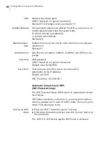
SSID

Name of the access point

(ASCII characters, no special characters). 

Standard: Tixi-Devtype-serial, see chapter 5.1

EnableOnStartup

This parameter determines whether the WiFi access point is au-

tomatically activated when the system starts. 

0=do not activate automatically

1=activate automatically

Standard: 0

AllowedConnec-

tions

Defines how many concurrent client connections are allowed.

maximum: 5

Standard: 1

Authentication

Specifies the encryption method. Currently only WPA2 is sup-

ported.

Password

WiFi password

(ASCII characters, no special characters). 

Default value: berlin2000

Host name

Host name via which the device can be reached

(alternative to the IP address).

Default: see SSID
WiFi IP address: 192.168.100.1

Automatic connection via WPS

(WiFi Protected Setup) 

The WiFi Protected Setup (WPS) option is supported in Access 

Point Mode. 
WPS allows automatic connection to an access point without 

entering a password. To switch to WPS mode, the access point 

mode must already be active.

 Turning on WPS

mode

Press the "WiFi" button for about 1 second.

Hold down the button and then press the "Service" button at 

the same time. 

The "WiFi On" LED flashes rapidly. WPS mode is activated. 

Summary of Contents for 50.0070.0001.00

Page 1: ...Configuration manual FP S ENGuard ...

Page 2: ...iguration manual FP S ENGuard 2 FP InovoLabs GmbH Prenzlauer Promenade 28 13089 Berlin Germany Telephone 49 0 30 220 660 601 E mail info inovolabs com Website www inovolabs com 2020 FP InovoLabs GmbH Berlin ...

Page 3: ...________14 4 4 Socket for backup battery ________________________________________________15 5 Ethernet connection__________________________________________________________ 16 5 1 Initial start up and access ________________________________________________16 5 1 1 IP address of the device _________________________________________16 5 1 2 Access to the web server ____________________________________...

Page 4: ..._________ 45 6 16 Internal temperature sensor _____________________________________________ 46 6 17 Digital inputs 24 V Model series W550 and W667 ______________________ 47 6 18 Digital outputs 48 V 120 mA Model series W550 _______________________ 48 6 19 Relay outputs 30 V 2 A Model series W667 _____________________________ 49 7 Expansion modules __________________________________________________...

Page 5: ..._______________________84 7 8 1 Restrictions for the operation of passive sensors ________________89 7 9 S1 D30G 3 digital inputs galvanically isolated __________________________90 8 Index __________________________________________________________________________ 93 ...

Page 6: ...ntains important information for your safety and describes the configuration of the devices from the following model series FP S ENGuard W550 in this manual W550 FP S ENGuard W640 in this manual W640 FP S ENGuard W667 in this manual W667 Prerequisites The FP S ENGuard is mounted on the wall and electrically con nected as described in the Installation and Safety instructions supplied with the devic...

Page 7: ...olours and safety signs identify the warning instructions and additional information in the set of documentation for the FP S ENGuard devices Warning of immediate danger to life or serious injury Warning of potential danger to life or serious injuries Warning of potential minor injuries Notice of potential damage to property Damage to the device the software or other material assets A useful tip r...

Page 8: ...P S ENGuard only as described in the Installation and Safety manual and this configuration manual Do not carry out any unauthorised interventions in the hardware and software 2 2 Safety instructions for working on an already installed FP S ENGuard Hazardous areas with live parts When working on an already installed FP S ENGuard there are areas where there is a hazard of electric voltage Inside the...

Page 9: ...in enclosed and clean spaces Avoid harmful environmental conditions such as heat sunlight strong shocks and vibrations Please note the special instructions for handling the SIM card Protect the interfaces from electrical damage by avoiding mixing up connections Use a torque screwdriver to avoid mechanical damage to the connections Protect the outputs from destruction by observing the maximum outpu...

Page 10: ...1 00 FP S ENGuard W640 NB 50 0070 0013 00 FP S ENGuard W640 BB 50 0070 0014 00 FP S ENGuard W667 LAN 50 0070 0021 00 FP S ENGuard W667 NB 50 0070 0023 00 FP S ENGuard W667 BB 50 0070 0024 00 GETEC FP S ENGuard W550 BB 50 0170 0001 00 Legend Standard N Number Not available W550 LAN W550 NB W550 BB W640 LAN W640 NB W640 BB W667 LAN W667 NB W667 BB Built in power supply unit 110 V 240 V CPU 400 MHz A...

Page 11: ...s 24 V 5 5 5 Digital outputs 1 1 1 Analogue inputs 4 4 4 Analogue outputs 3 3 3 Relay outputs 2 2 2 2 2 2 Relay outputs make contacts 3 3 3 S0 Pulse inputs 3 3 3 Pt1000 Sensor inputs 2 2 2 Temperature sensor 1 Wire built in Socket for S1 Expansion module 1 1 1 5 5 5 2 2 2 Ethernet connection Antenna connection UMTS Modem LTE Modem Legend Standard N Number Not available W550 LAN W550 NB W550 BB W64...

Page 12: ...Configuration manual FP S ENGuard 12 4 Overview of all connections 4 1 Model series connection assignments W550 The illustration shows the FP S ENGuard W550 NB ...

Page 13: ...Overview of all connections 13 4 2 Model series connection assignments W640 The illustration shows the FP S ENGuard W640 BB ...

Page 14: ...Configuration manual FP S ENGuard 14 4 3 Model series connection assignments W667 The illustration shows the FP S ENGuard W667 BB ...

Page 15: ...se commercially available rechargeable batteries 1 2 V Please note that the M Bus does not work in rechargeable bat tery mode Variable Process SysIO P0 The loss of the energy supply can be detected via the system variable Process SysIO P0 With normal mains power supply the variable is set to 1 As soon as the power supply fails the var iable changes to 0 Via an appropriately programmed EventState E...

Page 16: ...o PC The device tries to obtain an IP address from a DHCP server for about 30 seconds after turning on If it has not received an an swer after 30 seconds the device s LAN LED flashes and the de fault IP address is set as follows Network with DHCP server In a network with DHCP server the host name is formed ac cording to the following scheme Tixicom Devtype serial applies to LAN and WiFi Key figure...

Page 17: ...umber 04240361 Tixicom WT667 04240361 If you have integrated the device into a domain network with DHCP server it is usually necessary to add the local address of your domain network to the host name In the Tixi Com corporate network for example Tixicom WT667 04240361 tixicom local 5 1 2 Access to the web server On delivery and after a factory reset a standard website is in stalled To access the d...

Page 18: ...splays a variety of information on the hardware and configuration of the device Additionally the configuration System config button and the process data System properties button of the connected sensors meters PLCs etc if configured can be displayed in separate windows ...

Page 19: ...host name of the device in the IP Settings section If the Tixi WLAN stick option has been selected the IP address is already preset and need not be adjusted Now click on the Connect button When the connection has been successfully established this is signalled at the upper right edge of TILA GPRS Internet LAN for connections via the LAN port of the device Tixi WLAN stick for connections via WiFi w...

Page 20: ...Enter the IP address or the host name in the dialogue and click OK Example Connection via WiFi stick If the Online option in the middle of the TICO window is ac tivated deactivate the option with a single mouse click Click on the Port menu item and select TCP IP After the connection has been successfully established the Online option is activated ...

Page 21: ...per side and keep it pressed Switch on the device Wait until the Power LED yellow flashes Release the Service button briefly Press the Service button again Keep it pressed until the Power LED flashes rapidly Release the Service button The device boots up All settings in the device have now been successfully reset to factory defaults The only exception is the SIM PIN This is also retained after a f...

Page 22: ... 2 or a USB stick 6 2 RS485 Interfaces COM2 COM5 model dependent Key figures at a glance ITU T V 24 V 28 with handshake Maximum transmission distance 12 m 5 spring terminals each max 230 400 bps Signals RTS CTS GND Rx Tx Name of the connection terminal for COM1 KX1 all models Name of the connection terminal for COM4 KX2 optional Key figures at a glance In accordance with EIA TIA 485 maximum transm...

Page 23: ... pulse inputs are de scribed in the chapter 7 2 Key figures at a glance W600 models M Bus master for 50 slaves optional 100 Slaves W500 models M Bus master for 25 slaves Open circuit voltage 36 V Ri approx 20 Ω Short circuit proof galvanic isolation 1 500 V W600 models max bus length 50 m grid dimension 3 81 mm cross section max 1 5 mm W500 models max bus length 50 m grid dimension 5 08 mm cross s...

Page 24: ...branch Process MB IO Q P0 _ 0 P1 _ 1 Q QB P0 _ 2 QB QW P0 _ 2 QW QD P0 _ 2 QD IO MB Process Example Turning on normally open contact relay 1 Set _ Process MB IO Q P0 value 1 ver y Key figures at a glance 2x relay changeover contact 230 V AC 5 A or 110 V DC 0 3 A Name of connection terminals Relay 1 KP2 relay 2 KP4 ...

Page 25: ...n the process branch Process MB IO I P0 _ 1 P1 _ 1 I IB P0 _ 3 IB IW P0 _ 3 IW ID P0 _ 3 ID IO MB Process Example Read the second 240 V input Get _ Process MB IO I P1 ver y Key figures at a glance 2x digital input each 230V AC 3A Ri 54 kΩ Name of connection terminal KP3 input 1 KP5 input 2 ...

Page 26: ...ard P Pt1000 S System reference voltages B Battery voltage of the backup battery Process Function Value range Technical data P0 to P3 Analogue inputs channel 1 to 4 0 to 4095 0 to 10 V Ri 100 kΩ 0 to 20 mA Ri 100 Ω P4 Temperature sensor onboard Values in milli degrees Celsius 40 to 125 C Resolution 0 1 C P5 P6 P10 P11 Pt1000 raw value input 1 and 2 Pt1000 values in milli degrees Celsius 0 to 4095 ...

Page 27: ...0 to 20 mA Ri 100 Ω Current input active 0 to 20 mA Module address C092 Name of connection terminals AI_1 1 to AI_4 2 Input Operating mode Switch position Peripheral configuration AI_1 0 to 10 V SA1 P SA2 P None AI_1 0 to 20 mA passive SA1 P SA2 P InputMode0 _ I AI_1 0 to 20 mA active SA1 P SA2 A InputMode0 _ I AI_2 0 to 10 V SA3 P SA4 P None AI_2 0 to 20 mA passive SA3 P SA4 P InputMode1 _ I AI_2...

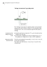
Page 28: ...setting Activation of the voltage measure ment Set both switches of a channel to P e g for channel AI_1 the switches SA1 and SA2 Configure the InputMode for the according input to U in the peripheral configuration or leave out the InputMode Assignment of the screw terminals The left screw terminal of an input AI_1 1 AI_2 1 AI_3 1 AI_4 1 is the earth connection The right screw terminal AI_1 2 AI_2 ...

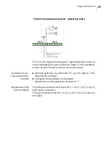
Page 29: ...e measured Activation of pas sive current meas urement Set both switches of a channel to P e g for input AI_1 the switches SA1 and SA2 Configure the peripheral configuration InputMode for the respective channel to I Assignment of the screw terminals The left screw terminal of an input AI_1 1 AI_2 1 AI_3 1 AI_4 1 is the earth connection The right screw terminal AI_1 2 AI_2 2 AI_3 2 AI_4 2 is the cu...

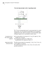
Page 30: ...y voltage of approx 24 V is provided for each sensor Activation of ac tive current meas urement Set both switches of an input to A e g for input AI_1 the switches SA1 and SA2 Configure the peripheral configuration InputMode for the respective input to I Assignment of the screw terminals The left screw terminal of an input AI_1 1 AI_2 1 AI_3 1 AI_4 1 is the negative connection The right screw termi...

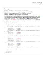
Page 31: ... to 10000 mV or 0 to 20000 corresponds to 0 to 20000 µA is done via the PROCCFG database SetConfig _ PROCCFG Periphery Module Name ADC 8 12bit Address C092 Channel 0 Analogue Input 1 Voltage Measurement 0 10000 Numerator0 _ 10000 Denominator0 _ 3943 Channel 1 Analogue Input 2 Current Measurement passive 0 20000 Numerator1 _ 20000 Denominator1 _ 3315 InputMode1 _ I Channel 2 Analogue Input 3 Curren...

Page 32: ... C092 AI_AAAATPPSSB P3 The values for Tolerance can be specified separately for each channel Tolerance0 _ 5 Tolerance1 _ 1 Tolerance2 _ 10 Tolerance3 _ 2 If the channel related values for Tolerance are used the global setting for Tolerance must no longer be used within a Module definition The Rate parameter can be used to set the sample rate in mil liseconds for all channels Default value is 1000 ...

Page 33: ...is approx 80 C to 190 C The AD converter works with 12 bit resolution The raw values range from 0 to 4095 Example Process branch with a connected Pt1000 sensor P5 P10 C092 AI_AAAATPPSSB P0 _ 4 P1 _ 4 P2 _ 4 P3 _ 4 P4 _ 28200 P5 _ 1100 P6 _ 2497 P7 _ 1003 P8 _ 1504 P9 _ 4090 P10 _ 24528 P11 _ 361494 AI_ AAAATPPSSB C092 Key figures at a glance 2x Pt1000 inputs Module address C092 Name of connection ...

Page 34: ... raw value P5 is 1100 The converted value P10 is 24528 milli degrees Celsius The Pt1000 input 2 P6 is open in the example In this case the maximum value 4095 and the converted value P11 405866 is displayed When the input is open the converted value P10 P11 may vary approximately 1 ...

Page 35: ...A converter 4006 SetConfig _ PROCCFG ver y Periphery Analogue output 1 with module address C010 Max raw value of the D A converter 4006 The range 0 4095 is scaled to 0 2000 in this case Module Name DAC 1 12bit Address C010 Channel 1 Analogue Output 1 Numerator0 _ 4006 Denominator0 _ 2000 Tolerance _ 1 Rate _ 1000 Module Periphery SetConfig Key figures at a glance 3x analogue outputs Voltage output...

Page 36: ...ways DAC 1 12Bit The first output has the address C010 and is displayed in the process branch as follows C010 AO P0 _ 1000 AO C010 The second output has the address C012 and is displayed in the process branch as follows C012 AO P0 _ 1000 AO C012 The third output has the address C014 and is displayed in the process branch as follows C014 AO P0 _ 1000 AO C014 ...

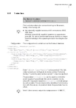
Page 37: ...rial 000000fbbb1d Temperature_0 Name Temp_0 _ DW simpleType Int32 Device Device Name Device_1 _ 1 family 28 serial 000000fc8b96 Temperature_1 Name Temp_1 _ DW simpleType Int32 Device Bus External SetConfig Enter 1Wire type master as bus protocol The indi vidual sensors are configured via device entries The family family and the serial number serial must be specified The parameter StrongPullup can ...

Page 38: ...he Sensor Value and the ExtPower operating mode 0 parasitic 1 fed The values returned by ScanDevices can then be transferred to the External SetConfig _ PROCCFG ver v External Bus Name Bus0 _ 1Wire protocol 1Wire type master Device Name Device_0 _ 0 family 10 serial 000802bdfa08 Temperature_0 Name Temp_0 _ DW simpleType Int32 Device Device Name Device_1 _ 1 family 28 serial 00000556b8d5 Temperatur...

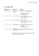
Page 39: ...vailable 0 No mains power supply in battery mode Process SysIO P1 1 wire overload 1 1 wire overloading short circuit too many sensors 0 no overloading Process SysIO P2 M Bus overload 1 M Bus overloading short circuit too many meters 0 no overloading Process SysIO P3 Battery charging 1 Rechargeable battery is being charged 0 Charging completed Process SysIO P4 Rechargeable battery voltage Rechargea...

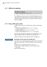
Page 40: ... Tixi Gate_FW tar gz file Debug recordings via debtrace txt file Archiving of log data via the WriteFile command The USB stick should be formatted with the FAT32 file system Only one partition may be contained on the USB stick When the USB stick is mounted the WiFi LED lights up Damage to the file system on the USB stick If the stick is not removed properly the file system on the USB stick may be ...

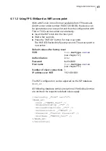
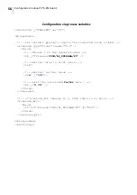
Page 41: ...ry second The access point is now active The WiFi configuration can be adjusted via the ISP database WLAN_AP All following database entries are optional If individual entries are omitted the respective default values apply SetConfig _ ISP ver v WLAN_AP SSID _ WE550_Test EnableOnStartup _ 0 AllowedConnections _ 1 Authentication _ WPA2 Password _ Secret Password HostName _ WE550_Test WLAN_AP SetConf...

Page 42: ...y only WPA2 is sup ported Password WiFi password ASCII characters no special characters Default value berlin2000 Host name Host name via which the device can be reached alternative to the IP address Default see SSID WiFi IP address 192 168 100 1 Automatic connection via WPS WiFi Protected Setup The WiFi Protected Setup WPS option is supported in Access Point Mode WPS allows automatic connection to...

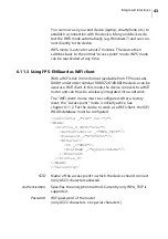
Page 43: ... client In this mode the device connects to a WiFi router and can thus be wirelessly integrated into a network The WiFi client mode must be configured After a factory reset the Access point mode is initially active See chapter 6 11 2 For the device to work as a WiFi client the ISP WLAN database must be configured SetConfig _ ISP ver y WLAN Profile_0 SSID acer Authentication _ WPA_TKIP Password _ 8...

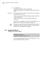
Page 44: ... Wait a few seconds The WiFi LED flashes briefly every second The device is now logged on to the router If the WiFi LED is not flashing check the settings especially the password Simultaneous use of the LAN interface and WiFi client mode on the same network both wireless connection and LAN cable to the WiFi router is currently not supported 6 12 Supply 24V 50 mA Model series W640 W667 A 24 V suppl...

Page 45: ...ection to a PC are available from FP InovoLabs GmbH 6 14 Reset button The device can be manually restarted hardware reset by press ing button S4 This button is intended for developers 6 15 Power LED The Power LED lights up red when the device is supplied with mains voltage Key figures at a glance Name of connection terminal DBG Key figures at a glance Name of the button S4 Key figures at a glance ...

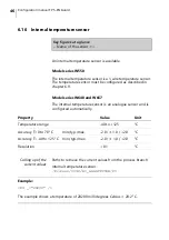
Page 46: ...ure sensor is an analogue sensor and is configured automatically Calling up of the current values Paths to retrieve the current values from the process branch Internal temperature sensor Process C092 AI_AAAATPPSSB P0 Example P4 _ 28200 The example shows a temperature of 28200 milli degrees Celsius 28 2 C Key figures at a glance Name of the sensor TS Property Value Unit Temperature range 40 to 125 ...

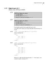
Page 47: ...r v Answer exemplary Get I P0 _ 0 P1 _ 0 I Get W667 Get _ Process C040 I ver v Answer exemplary Get I P0 _ 0 P1 _ 0 P2 _ 1 P3 _ 0 P4 _ 1 I Get When not connected the input shows a 1 If an input is con nected to earth it shows a 0 W550 key figures at a glance 2x digital inputs Module address MB IO I Name of connection terminal Dig In W667 key figures at a glance 5x digital inputs Module address C04...

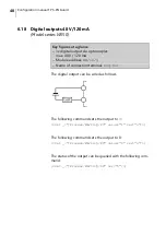
Page 48: ...output to 1 Set _ Process MB IO Q P0 value 1 ver v The following command sets the output to 0 Set _ Process MB IO Q P0 value 0 ver v The status of the output can be queried with the following com mand Get _ Process MB IO Q P0 ver v Key figures at a glance 1x digital output via optocoupler max 48 V 120 mA Module address MB IO Q Name of connection terminal Dig Out ...

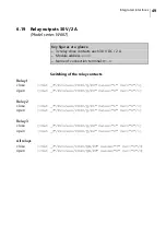
Page 49: ...tion terminal M5 X Relay 1 close Set _ Process C040 Q P0 value 1 ver v open Set _ Process C040 Q P0 value 0 ver v Relay 2 close Set _ Process C040 Q P1 value 1 ver v open Set _ Process C040 Q P1 value 0 ver v Relay 3 close Set _ Process C040 Q P2 value 1 ver v open Set _ Process C040 Q P2 value 0 ver v All relays close Set _ Process C040 QB P0 value 7 ver v open Set _ Process C040 QB P0 value 0 ve...

Page 50: ...Configuration manual FP S ENGuard 50 Representation on the process branch Process C040 Q P0 _ 0 P1 _ 1 P2 _ 1 Q QB P0 _ 6 QB QW P0 _ 6 QW QD P0 _ 6 QD C040 Process ...

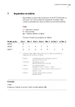
Page 51: ...del series all 5 sockets are permanently equipped with expansion modules Example C694 Expansion module in socket 5 with module address 94 Model series Slot 1 Slot 2 Slot 3 Slot 4 Slot 5 L2 Slot 1 L2 Slot 2 W550 0 W640 2 3 4 5 6 W667 0 0 0 0 0 5 6 Socket 1 2x Pt1000 Inputs for temperature sensors Address C092 P5 P6 Socket 1 2 4x analogue inputs Address C092 P0 P1 P2 P3 Socket 3 3x analogue outputs ...

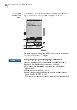
Page 52: ...rs are located directly on the L2 adapter Damage to property due to improper installation Improper installation of the expansion modules can lead to damage to the device or the expansion modules Only install the expansion modules when the device is switched off Make sure the polarity is correct Always set the default addresses with the jumpers excep tions S1 AE3 S1 PT3 S1 S03 This way the expansio...

Page 53: ...to voltage values from 0 to 10 V and current values from 0 to 20 mA To scale the values to 0 to 10000 the PROCCFG database must be configured as follows the module is jumpered to address 94 in this case plugged into socket 5 therefore bus number 6 Key figures at a glance 3x analogue inputs resolution 11bit Voltage input 0 to 10V Ri 100 kΩ Current input passive 0 to 20mA Ri 120 Ω Default address fo...

Page 54: ..._ 10000 Denominator1_ 2047 Channel 3 Analogue Input 3 Numerator2_ 10000 Denominator2_ 2047 These values apply to all channels Tolerance_ 1 Rate_ 1000 Module Periphery SetConfig When setting 0 to 20 mA for the analogue inputs the periph eral database must be adapted e g NumeratorX _ 2000 De nominatorX _ 2047 X channel number 0 to 2 In this case the current value 0 to 20 mA is mapped to the values 0...

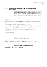
Page 55: ...Pressure sensor range from 0 to 6000 mbar at channel 1 of the internal analogue input Dmin 0 mbar 4 mA Dmax 6000 mbar 20 mA Maximum value of the analogue input 1994 raw value or 2000 scaled value see 7 1 Scaled values from 0 to 2000 thus correspond to 0 to 20 mA Scaled values from 0 2 2000 to 2000 then correspond to 4 to 20 mA AI 400 at 4 mA AI 2000 at 20 mA Calculation of the scaling factor AIcor...

Page 56: ...ssure type float format F 1 Value Channel 1 of the onboard module LD _ Process C094 AI_PPSSAAA P0 Restore value to float stack I2F Subtract initial value SUBF _ 400 enter the calculated factor here P2 _ 3 75 Value Pressure if Pressure_Err changes to 1 then there is an error Pressure_Err Value LT v1 Process C094 AI_PPSSAAA P0 v2 400 Value Pressure_Err ProcessVars SetConfig ...

Page 57: ...y is then saved either cyclically via an internal configurable timer or a synchronous pulse at one of the pulse inputs into an internal read only variable which can then be used as a source for data logging or EventHandler For example the measuring pulse of the power supply can be used as an external synchronous pulse Key figures at a glance 3x pulse inputs according to IEC 62053 31 for passive S0...

Page 58: ...58 Please note There are 2 hardware versions V1 0 and V2 0 Jumper settings for hardware version V2 0 Address PX1 PX2 0x3E 0x3C 3 4 0x3A 1 3 0xB0 1 2 0xB2 3 4 1 2 0xB4 1 3 1 2 0xB6 3 4 0xB8 3 4 3 4 0xBA 1 3 3 4 Module address w o jumper ...

Page 59: ...played count value is always the number of pulses during the last measuring cycle The counting registers are cleared under the following circum stances A configuration with off off off mode is imported When the system is restarted in rel mode 0xBC 1 2 3 4 0xBE 3 4 1 2 3 4 0xC0 1 3 1 2 3 4 0xC2 5 6 0xC4 3 4 5 6 0xC6 1 3 5 6 0xC8 1 2 5 6 0xCA 3 4 1 2 5 6 0xCC 1 3 1 2 5 6 0xCE 1 2 5 6 0xD0 3 4 3 4 5 ...

Page 60: ...Value Numerator3 _ Numerator Denominator3 _ Denominator StartValue3 _ StartValue Module Periphery SetConfig Module Identifies the module Elements Name S0 PIC predefined Address Cbaa b Bus number aa Module address Jumper Mode Defines the Pulse Interface Mode sync1 off abs rel Channel 1 synchronised Channel 2 channel 3 is off absolute or relative or sync2 Channel 1 synchronises channels 2 and 3 or o...

Page 61: ...ptional X 1 3 Specifies the start value for each channel abs Absolute count synchronised by SyncPeriod During synchronisation the counted value is copied into a read only variable and the internal channel counter is not reset rel Relative count synchronised by SyncPeriod During synchronisation the counted value is copied into a read only variable and the internal channel counter is reset to 0 sync...

Page 62: ...start value P1 Channel 2 Counted pulses converted with numerator and denomi nator plus start value P2 Channel 3 Counted pulses converted with numerator and denomi nator plus start value P3 Channel 1 Counted pulses without start value P4 Channel 2 Counted pulses without start value P5 Channel 3 Counted pulses without start value P6 Time since the last synchronisation event in seconds P7 ChangeToggl...

Page 63: ...ered with 3 channels has module address 0x3E bus 0 Channel 1 absolute counting Channel 2 relative counting Channel 3 is not used Scaling for channel 2 with 4 1 Synchronisation every 5 minutes 300s The range 0 4095 is scaled to 0 2000 in this case SetConfig _ PROCCFG ver y Periphery Module Name S0 PIC Address C03E Mode _ abs rel off SyncPeriod _ 300 Numerator1 _ 1 Denominator1 _ 1 Numerator2 _ 4 De...

Page 64: ... 400 P2 _ 0 P3 _ 100 P4 _ 100 P5 _ 0 P6 _ 300 P7 _ 0 1 if read within 1 second after synchronisation P8 _ 3 Counter C03E Values in the second cycle after 50 pulses on both channels in the process branch C03E Counter P0 _ 150 P1 _ 200 P2 _ 0 P3 _ 150 P4 _ 50 P5 _ 0 P6 _ 300 P7 _ 0 1 if read within 1 second after synchronisation P8 _ 3 Counter C03E ...

Page 65: ...S0 PIC Address C63C Mode _ sync1 abs SyncPeriod _ 900 Numerator1 _ 1 Denominator1 _ 1 Numerator2 _ 1 Denominator2 _ 1 Numerator3 _ 1 Denominator3 _ 1 StartValue3 _ 1400 Module Periphery SetConfig Values in the process branch for the first cycle after 100 pulses on channel 2 and 3 For simplification it should be assumed that the synchronous pulse for channel 1 oc curs simultaneously with the intern...

Page 66: ... within 1 second after synchronisation P8 _ 3 Counter C63C Using the S0 inputs as digital inputs The three S0 inputs can also be used as normal digital inputs In this case the inputs are switched passively e g passive contact such as relays or buttons This does not require any configura tion to be transferred to the device The digital input values of the three S0 inputs are mapped in the process b...

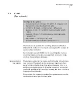
Page 67: ...2 The jumpers and some other components may be arranged dif ferently depending on the module type e g S1 D30G Module address Module type Pin assignment on screw terminal S1 D50 GND IN0 IN1 IN2 IN3 IN4 S1 D30G IN1 IN1 IN2 IN2 IN3 IN3 S1 D05 GND OUT0 OUT1 OUT2 OUT3 OUT4 S1 D03G OUT0 OUT1 OUT2 Standard module address x40 all jumpers set to 0 Please always set all jumpers 0 or 1 ...

Page 68: ...puts Configuration of the modules is not necessary Key figures at a glance 5x digital inputs for potential free contacts relays or digital signals Low 0 to 1 V High 3 5 V 24 V Internal pull up approx 2 kΩ Default module address 0x40 all jumpers JP1 to JP3 set to 0 ...

Page 69: ... 69 Representation of the inputs on the process branch Example Module S1 D50 module address 0x40 socket 2 bus 3 Process C340 I P0 _ 1 P1 _ 1 P2 _ 1 P3 _ 1 P4 _ 1 I IB P0 _ 31 IB IW P0 _ 31 IW ID P0 _ 31 ID C340 Process ...

Page 70: ... digital outputs Key figures at a glance 5x digital outputs optocoupler with common earth earth is connected to device earth Dielectric strength 48 V max current 120 mA OnResistance approx 25 Ω Default module address 0x40 all jumpers JP1 to JP3 set to 0 ...

Page 71: ... 71 Representation of the outputs on the process branch Example Module S1 D05 module address 0x40 socket 1 bus 2 Process C240 Q P0 _ 1 P1 _ 0 P2 _ 1 P3 _ 1 P4 _ 0 Q QB P0 _ 31 QB QW P0 _ 31 QW QD P0 _ 31 QD C240 Process ...

Page 72: ...gital outputs galvanically isolated Key figures at a glance 3 independent digital outputs electrically isolated via optocoupler Dielectric strength 48 V max current 100 mA OnResistance approx 25 Ω Default module address 0x40 all jumpers JP1 to JP3 set to 0 ...

Page 73: ... modules 73 Representation of the outputs on the process branch Example Module S1 D03G module address 0x42 socket 4 bus 5 Process C542 Q P0 _ 0 P1 _ 0 P2 _ 0 Q QB P0 _ 0 QB QW P0 _ 0 QW QD P0 _ 0 QD C542 Process ...

Page 74: ...e conversion from voltage U mV to degrees Celsius is auto matic The raw value of the A D converter is not displayed The display in the process branch is in milli degrees m C Key figures at a glance 3x Pt1000 inputs Default module address 0x96 Module Address no jumper ...

Page 75: ...0 _ 0 P1 _ 22410 P2 _ 0 I C596 Process In the example above the value 22410 milli degrees Celsius 22 41 C is displayed for the Pt1000 temperature sensor at input 2 the other PT1000 temperature sensors show the value 0 If no Pt1000 temperature sensor is connected a value of ap prox 199996 is displayed Please do not use module addresses x90 and x94 ...

Page 76: ...onfiguration manual FP S ENGuard 76 7 5 S1 WL2 2 relay outputs changeover contact Key figures at a glance 2x relay outputs changeover contacts Maximum 48 V 3 A Default module address 0x42 Module Address ...

Page 77: ...tputs on the process branch Example Module S1 WL2 module address 0x42 socket 5 bus 6 Process C642 Q P0 _ 0 P1 _ 1 Q C642 Process In the example the normally open contact of relay 1 is open NO1 and the normally open contact of relay 2 is closed NO2 ...

Page 78: ...ia jumpers The factory setting is 0 to 10 V The D A converters of the analogue outputs use raw values be tween 0 and 4035 corresponds to 0 to 10 V Key figures at a glance 2x analogue outputs resolution 12bit Voltage output 0 to 10 V Ri 100 kΩ Current output 0 to 20 mA Ri 120 Ω Default address for automatic detection 0x18 0x1A Not allowed ...

Page 79: ...Expansion modules 79 Representation of the outputs on the process branch Example Module S1 AA2 address 0x10 0x12 socket 5 bus 6 Output 1 C610 AO P0 _ 1000 AO C610 Output 2 C612 AO P0 _ 1000 AO C612 ...

Page 80: ...to 2000 maximum raw value of the D A converter 4027 SetConfig _ PROCCFG ver y Periphery S1 AA2 in Slot 5 with module address C618 Raw value of the D A converter at 20 mA 4027 The range 0 4027 is scaled to 0 2000 in this case Module Name S1 AA2 Address C618 Channel 1 Analogue Output 1 Numerator0 _ 4035 Denominator0 _ 2000 Tolerance _ 1 Rate _ 1000 Module Periphery SetConfig ...

Page 81: ... The electrical characteristics and programming are identical to module S1 AE3 V1 0 Key figures at a glance 3x analogue inputs resolution 11bit Voltage input 0 to 10 V Ri 100 kΩ Current input passive 0 to 20 mA Ri 120 Ω Default address for automatic detection 0x92 Module Address no jumper Not allowed Channel 1 Jumper off voltage U Jumper on current I Channel 2 Channel 3 ...

Page 82: ...he values to 0 to 10000 the PROCCFG database must be configured as follows The module is jumpered to address 94 in this case plugged into socket 5 therefore bus number 6 SetConfig _ PROCCFG ver y Periphery Module Name S1 AE3 Address C694 Channel 1 Analogue Input 1 In0 Numerator0_ 10000 Denominator0_ 2029 Channel 2 Analogue Input 2 In1 Numerator1_ 10000 Denominator1_ 2029 Channel 3 Analogue Input 3...

Page 83: ...00 mV socket 4 bus 5 Process C592 AI_AAA P0 _ 5000 P1 _ 2500 P2 _ 0 AI_AAA C592 Process Material damage due to incorrect installation of the modules Incorrect installation of the modules may result in material damage to the expansion modules Make sure that the polarity of the modules is correct Please do not use the module addresses x90 and x92 ...

Page 84: ...ve can be measured The operating mode is selected via 9 jumpers Key figures at a glance 3x analogue inputs resolution 11bit Voltage input 0 to 10 V Ri 100 kΩ Current input 0 to 20 mA Ri 120 Ω Current input active 0 to 20 mA Default address for automatic detection 0x92 Module Address no jumper Not allowed Channel 1 Jumper off voltage U Jumper on current I Channel 2 Channel 3 passive active ...

Page 85: ...the screw terminals The A D converters of the analogue inputs provide raw values between 0 and 2029 This corresponds to voltage values from 0 to 10 V and current values from 0 to 20 mA To scale the values to 0 to 10000 the PROCCFG database must be configured The module is jumpered to address 94 plugged into socket 5 therefore bus number 6 SetConfig _ PROCCFG ver y Periphery Module Name S1 AE3 Addr...

Page 86: ... C592 AI_AAA P0 _ 5000 P1 _ 2500 P2 _ 0 AI_AAA C592 Process Measurement Input 1 5000 mV Input 2 2500 mV Input 3 0 mV Material damage due to incorrect installation of the modules Incorrect installation of the modules may result in material damage to the expansion modules Make sure that the polarity of the modules is correct Please do not use the module addresses x90 and x92 ...

Page 87: ...ry setting The left screw terminal of a channel K1 1 K2 1 K3 1 is the earth connection the right screw terminal K1 2 K2 2 K3 2 is the voltage input The two pin upper jumper must be open For the three pin lower jumpers the upper two contacts must be connected Current measure ment passive Voltage Earth Voltage measurement Current Earth Current measurement ...

Page 88: ...t range of 4 to 20 mA see chapter 7 1 Current measure ment active In the Current measurement active mode for current loop sensors a current limited voltage of approx 24 V is provided The left screw terminal of a channel K1 1 K2 1 K3 1 is the neg ative input the right screw terminal K1 2 K2 2 K3 2 is the cur rent input The two pin upper jumper must be closed For the three pin lower jumpers the lowe...

Page 89: ...el series W640 W667 If the 24V terminal KP24 is loaded and the integrated ana logue outputs are not operated as current outputs max 1 module S1 AE203 S1 AE3 P can be used If the 24V terminal KP24 is not loaded and the integrated an alogue outputs are not operated as current outputs max 2 modules S1 AE203 S1 AE3 P can be used FP S ENGuard Model series W550 The S1 AE203 S1 AE3 P modules can only be ...

Page 90: ... up red at high level Configuration of the modules is not necessary Key figures at a glance 3x digital inputs galvanically isolated Low 0 to 9 2 V High 10 4 V to 60 V Maximum input voltage 60 V to 60 V Input current 2 2 to 3 1 mA Creepage and clearance distance between individual inputs 0 8 mm Creepage and clearance distance between external input and internal circuit 2 2 mm Default module address...

Page 91: ...d as 0 When the high level is reached the display changes to 1 Representation of the inputs on the process branch Example Module S1 D50 module address 0x40 socket 2 bus 3 Process C340 I P0 _ 1 P1 _ 0 P2 _ 1 I IB P0 _ 5 IB IW P0 _ 5 IW ID P0 _ 5 ID C340 Process In the example shown above input 1 In1 and input 3 In3 are at high level and input 2 In2 at low level ...

Page 92: ...Configuration manual FP S ENGuard 92 ...

Page 93: ...terminals 30 Current measurement passive 29 Activation 29 Assignment of the screw terminals 29 D Debug port 45 Declaration of conformity 6 Digital inputs S1 D30G 90 S1 D50 68 use S0 inputs 66 W640 W667 25 Digital inputs 24 V 47 Digital inputs and outputs S1 Dxx 67 Digital outputs S1 D03G 72 S1 D05 70 Digital outputs 48 V 120 mA W550 48 Documents other 6 E Expansion modules 51 L2 Adapter W667 only ...

Page 94: ... as a digital input 66 S0 Pulse inputs W550 23 S1 AA2 78 S1 AE3 V1 0 53 S1 AE3 0 V2 0 81 S1 AE3 P V2 0 84 Current measurement active 88 Current measurement passive 87 Voltage measurement 87 S1 D03G 72 S1 D05 70 S1 D30G 90 Display of the logical levels 91 S1 D50 68 S1 Dxx 67 S1 PT3 74 S1 S03 57 S1 WL2 76 Safety instructions 8 Software TICO 20 TILA 19 Start up 16 Supply 24V 50 mA W640 W667 44 Switch...

Page 95: ...Index 95 W Web server 17 WiFi access point Using FP S ENGuard 41 WiFi client 43 Using FP S ENGuard 43 WiFi stick 41 order 41 1 wire bus 37 scanning 38 WPS 42 Turning on WPS mode 42 ...

Page 96: ...Notes 96 ...

Page 97: ...Notes 97 ...

Page 98: ...51 0070 9031 00 Rev 00 2020 08 xxx helbig berlin ...

Reviews: