


USER MANUAL
GATEWAY MEDIUM
Data connector for indoor and outdoor use
Ceruus Oy, ioLiving
Technical support:
1 (13)
ioliving.com
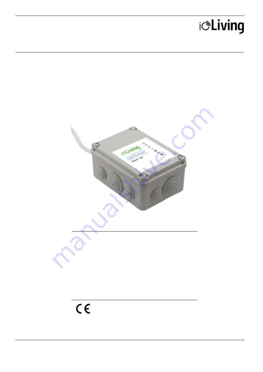
Gateway Medium
Data connector for indoor and outdoor use. Connected to the
Internet via a network cable (included) or wireless network.
In addition, an HDMI display and a USB keyboard are
required for connecting to a wireless network. The device is
used for continuous transfer of measured data to the ioLiving
cloud service.
Protection:
IP56, Protection against water jets
Temperature:
-20 °C – +60 °C
LoRa frequency: 871.5 MHz


