background image

NT301 OBDII/EOBD Code Reader User’s Guide_English Version_V1.00

8

2 Introduction

NT301 is developed by the most distinguished mind of the industry. It is specially designed to support
all 10 OBDII service modes, including live data, O2 sensor test and more, on OBDII/EOBD compliant
cars, SUVs, light-duty truck and mini-vans sold worldwide since 1996.

2.1 Code Reader Descriptions

This section illustrates external features, ports and connectors of the code reader.

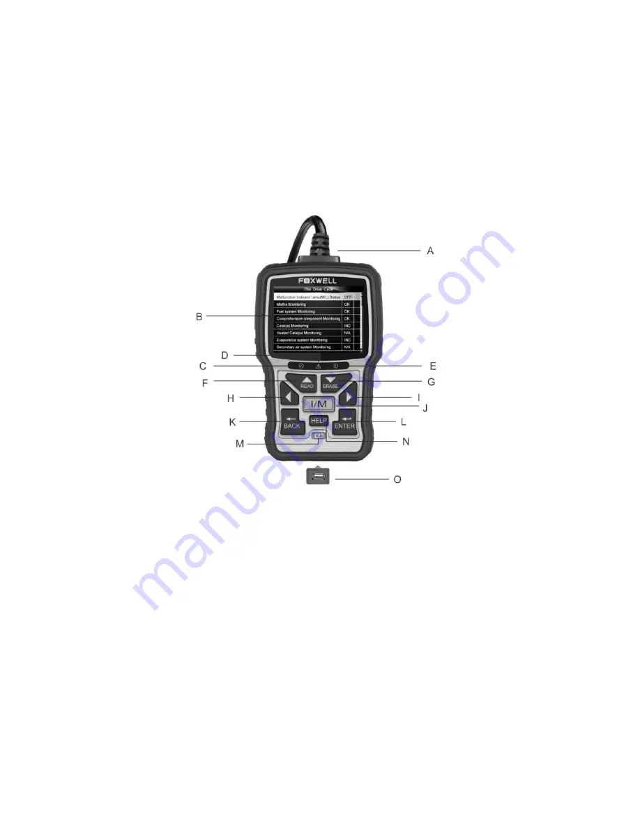
Figure 2-1 Front View

A.

OBD II Cable

- provides communication for vehicle DLC.

B.

LCD Display

- shows menus, test results and operation tips.

C.

Green LED Display

- indicates the engine system is working normally (all monitors on the

vehicles are active and performing their diagnostic testing), and no DTCs are found.

D.

Yellow LED Display

- shows the tool finds a possible problem. Pending DTCs exist or/and

some of the vehicle’s emission monitors have not run their diagnostic testing.

E

. Red LED Display

- indicates there are some problems in one or more of the vehicle’s systems.

In this case, the MIL lamp on the instrument panel is on.

F.

UP Key

- quick access to the Read Codes function before going to diagnostic menu and moves

selection up. When looking up DTC, it is used to change value of selected character.

G.

DOWN Key

- Quick access to the Clear Codes function before going to diagnostic menu and

moves selection down. When looking up DTC, it is used to change value of selected character.

H.

LEFT SCROLL KEY

- goes to previous character when looking up DTCs. Scrolls back and

forth through codes found and through different screens of data. Also it is used to make
selection of PIDs when viewing custom PID list, and to view PID graphs.

I.

RIGHT SCROLL KEY

- goes to next character when looking up DTCs. Scrolls back and forth

through codes found and through different screens of data. Also it is used to cancel all
selections of PIDs when viewing custom PID list.

J.

One Click I/M Readiness Key

- quick checks state emissions readiness and drive cycle

verification.

Summary of Contents for NT301

Page 1: ...holders Copyright Information 2014 Shenzhen Foxwell Technology Co Ltd All rights reserved Disclaimer The information specifications and illustrations in this manual are based on the latest information...

Page 2: ...fter the completion of service under this limited warranty 4 FOXWELL does not warrant uninterrupted or error free operation of the product If a problem develops during the limited warranty period the...

Page 3: ...NY OTHER LEGAL OR EQUITABLE THEORY EVEN IF FOXWELL KNEW OF THE LIKELIHOOD OF SUCH DAMAGES FOXWELL SHALL NOT BE LIABLE FOR DELAY IN RENDERING SERVICE UNDER THE LIMITED WARRANTY OR LOSS OF USE DURING TH...

Page 4: ...low all safety messages Do not route the test cable in a manner that would interfere with driving controls Do not exceed voltage limits between inputs specified in this user s manual Always wear ANSI...

Page 5: ...3 TECHNICAL SPECIFICATIONS 9 3 GETTING STARTED 9 3 1 PROVIDING POWER TO CODE READER 9 3 1 1 Connecting to Vehicle Power 9 3 1 2 Connecting to Personal Computer with USB Cable 9 3 2 APPLICATION OVERVIE...

Page 6: ...2 3 Allowed INC Monitors 37 7 2 4 Reset Factory Default 38 7 3 UNIT OF MEASURE 38 7 4 KEY BEEP SET 39 7 5 DIAG BEEP SET 41 7 6 TOOL SELF TEST 40 7 6 1 Display Test 41 7 6 2 Keypad Test 41 7 6 3 LED T...

Page 7: ...options displays Menu options include Languages Configure monitors Unit of measure Key Beep Set Diag Beep Set Tool self test 1 2 2 Arrow Icon An arrow icon indicates a procedure Example To change men...

Page 8: ...not run their diagnostic testing E Red LED Display indicates there are some problems in one or more of the vehicle s systems In this case the MIL lamp on the instrument panel is on F UP Key quick acce...

Page 9: ...re 20 to 70 4 to 158 Power Supply 8 18V vehicle power Supported Protocols J1859 41 6 J1850 10 4 ISO9141 KWP2000 ISO 14230 and CAN Control Area Network ISO 11898 Dimensions L W H 145 94 32mm Weight 0 6...

Page 10: ...ode reader Figure 3 1 Sample Home Screen 4 OBDII EOBD Operations OBD II EOBD menu lets you access all OBD service modes According to ISO 9141 2 ISO 14230 4 and SAE J1850 standards the OBD application...

Page 11: ...t on the display as illustrated below Figure 4 1 Sample System Status Screen NOTE If vehicle is equipped with more than one computer module for example a powertrain control module PCM and a transmissi...

Page 12: ...blinks Permanent Codes are DTCs that are confirmed and are retained in the non volatile memory of the computer until the appropriate monitor for each DTC has determined that the malfunction is no lon...

Page 13: ...s and no vital information will be lost before clearing codes There are two ways to erase codes Press the Erase hot key to erase codes from home screen Traditional way select Erase Codes from the diag...

Page 14: ...ata function allows real time viewing of the vehicle s electronic control unit s PID data including sensor data operation of switches solenoids and relays Menu options typically include Complete Data...

Page 15: ...ER key to display the datastream screen Figure 4 10 Sample View Data Menu Screen 4 Scroll with the up and down arrow keys to scroll through data to select lines and left and right arrow keys to scroll...

Page 16: ...list and focus on any suspicious or symptom specific data parameters To create a custom data list 1 Select Custom List from the menu and press the ENTER key Figure 4 13 Sample Live Data Menu Screen 2...

Page 17: ...E There are two types of trigger methods used Manual Trigger triggers recording whenever operators press the ENTER key DTC trigger automatically triggers recording when a code is detected by vehicle D...

Page 18: ...ata to set up Complete Data Set or Customer Data Set to record Figure 4 18 Sample Record Data Menu Screen 3 Scroll with the up and down arrow keys to pick a trigger mode and press the ENTER key to con...

Page 19: ...h an asterisk was picked a message prompting to erase data displays Figure 4 21 Sample Erase Recording Screen 5 If the recording is to be overwrited selected Yes if data is not to be overwrited pick N...

Page 20: ...and support a different number of PIDs Therefore the maximum number of frames that can be recorded varies The code reader keeps recording data until the memory is full the operator presses the BACK k...

Page 21: ...ample Record Data Screen 3 Press the UP DOWN key to view recorded PIDs of each frame Press the BACK key to exit Figure 4 27 Sample Record Data Screen 4 4 View Freeze Frame Freeze Frame menu displays f...

Page 22: ...ests on the emission system during normal driving conditions After a specific amount of drive time each monitor has specific driving conditions and time required the computer s monitors decide if the...

Page 23: ...build in beeper When the LED is Green Indicates that engine systems are OK and working properply the number of Monitors equipped with the vehicle which have run and performed their self diagnostic tes...

Page 24: ...1 Scroll with UP DOWN key to highlight I M Readiness from Diagnostic Menu and press the ENTER key If vehicle supports both types of monitors a screen for monitor type selection displays Select a monit...

Page 25: ...hen selected via the menu but tested when engine operating conditions are within specified limits If the vehicle uses a controller area network CAN protocol to communicate this function is not support...

Page 26: ...4 37 Sample data of 81 screen 5 Press the BACK key to exit and return 4 7 On Board Monitor Test The On Board Monitor Test function is useful after servicing or after clearing a vehicle ECU s memory It...

Page 27: ...2 Depending on the protocol the vehicle used one of these 2 screens shows Figure 4 39 Sample Non CAN Vehicle Test Screen Or Figure 4 40 Sample CAN vehicle test screen 3 Use the UP DOWN key to highlig...

Page 28: ...der User s Guide_English Version_V1 00 28 Figure 4 41 Sample Non CAN vehicle test screen For CAN vehicles test screen is illustrated as below Figure 4 42 Sample Can vehicle test screen 4 Press the BAC...

Page 29: ...to highlight a system or component press the ENTER key to start test and the code reader displays the message Command Sent Figure 4 44 Sample Component test screen 3 Press the BACK key to exit and ret...

Page 30: ...key Figure 4 45 Sample Diagnostic Menu Screen 2 Follow on screen instruction and send the command to read vehicle information A screen with a list of available options displays Figure 4 46 Sample Vehi...

Page 31: ...ight Modules Present from Diagnostic Menu and press the ENTER key Figure 4 48 Sample Diagnostic Menu Screen 2 A screen with the module IDs and protocols displays Figure 4 49 Sample Module Present Scre...

Page 32: ...ample DTC Lookup Screen 3 A screen with code number and its definition displays If definition could not be found SAE or Manufacturer Specific the code reader displays DTC definition not found Please r...

Page 33: ...the ENTER key Details of the test record displays View and analysis the recorded information then press BACK to exit 7 System Setup This section illustrates how to program the code reader to meet your...

Page 34: ...he ENTER key to confirm Press the BACK key to exit and return Figure 7 2 Sample Language Selection Screen 7 2 Configure Monitors This menu allows the users to configure the monitors required to test s...

Page 35: ...ensive Component Non Continuous Monitors NOTE Non continuous monitors are different for spark ignition cars gasoline engines and compression ignition card diesel engines Spark ignition vehicles Gas Ca...

Page 36: ...equired Monitors from menu and press the ENTER key to confirm 2 The custom monitors selection screen displays Figure 7 5 Sample Custom Monitors Selection Screen 3 Use the RIGHT key to select or desele...

Page 37: ...election screen displays and Use the RIGHT key to select or deselect a monitor or press the LEFT key to deselect all the monitors Press the ENTER key to confirm and BACK key to cancel Figure7 8 Sample...

Page 38: ...7 2 4 Reset Factory Default This menu will allow the users to restore the default configuration settings in the Configure Monitors menu and delete any customized settings In this case it will include...

Page 39: ...reen 7 3 Unit of measure Unit of measure opens a dialog box that allows you to choose between US customary or metric units of measure To change the unit setup 1 Scroll the UP DOWN keys to highlight Un...

Page 40: ...up Screen 2 Press the UP DOWN arrow key select an item and press the ENTER key to save and return Figure 7 15 Sample Beep Set Selection Screen 7 5 Diag Beep Set Key beep set opens a dialog box that al...

Page 41: ...pad and LED are working correctly Typical menu includes Display Test Keypad Test LED Test 7 6 1 Display Test Selecting Display Test option opens a screen that allows you to check the functionality of...

Page 42: ...keypad To test the keypad 1 Use the UP DOWN key to highlight Keyboard Test from Setup menu and press the ENTER key Figure 7 20 Sample Tool Self test Screen 2 Press any key to start test Key name or s...

Page 43: ...s to select the desired LED lamps to check The LED should turn on off according to the selected commands Figure 7 23 Sample LED Test Screen 4 To quit the test press the BACK key 8 Tool Information Sel...

Page 44: ...ctions Updating the Code Reader Printing Searching DTC Read the manuals Update tool settings 9 1 Updating the Code Reader NT301 is able to be updated to keep you stay current with the latest developme...

Page 45: ...o different ways for you to update the device Update online With internet connection the tool NT Wonder automatically detects the software version of the code reader and read the latest software versi...

Page 46: ...nstructed on page 44 of 9 1 Updating the Code Reader 2 Activate the application by clicking the Print Button from the menu Figure 9 4 Sample Printing Activation Function 3 Connect NT301 to computer wi...

Page 47: ...7 Sample Printing Data Screen 7 With the printer correctly connected use the Print key to print the testing data Press the BACK key to return to home screen 9 3 Searching DTC Searching DTC option ope...

Page 48: ...9 Sample User Manual Screen 9 5 Update Tool Settings Settings option opens a screen that allows you to set the language and style of the tool Still it offers the option for you to automatically check...

Reviews: