2
CONTENTS
1.
REVISION HISTORY
..................................................................... 3
2
PRODUCT OVERVIEW
................................................................... 4
3
SIGNAL DESCRIPTION
.................................................................. 5
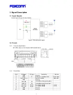
3.1
S
IGNAL
D
IAGRAM
........................................................................5
3.2
P
INOUTS
...............................................................................5
3.2.1
Connector Specification
.............................................................5
3.2.2
Pin definition
......................................................................5
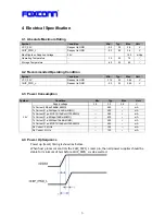
4
ELECTRICAL SPECIFICATION
............................................................ 6
4.1
A
BSOLUTE
M
AXIMUM
R
ATING
..............................................................6
4.2
R
ECOMMENDED
O
PERATING
C
ONDITION
.....................................................6
4.3
P
OWER
C
ONSUMPTION
...................................................................6
4.4
P
OWER
U
P
S
EQUENCE
...................................................................6
4.5
WLAN
RF
S
PECIFICATIONS
...............................................................7
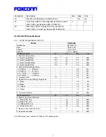
4.5.1
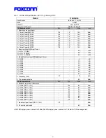
WLAN RF Specification- 802.11b
.....................................................7
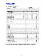
4.5.2
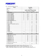
WLAN RF Specification- 802.11g
.....................................................8
4.5.3
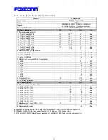
WLAN RF Specification- 802.11n (2.4GHz) HT20
.......................................9
4.5.4
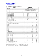
WLAN RF Specification- 802.11a
....................................................10
4.5.5
WLAN RF Specification- 802.11n (5GHz) HT20
.......................................11
4.5.6
WLAN RF Specification- 802.11n (5GHz) HT40
.......................................12
5
SCHEMATIC AND PCB LAYOUT
......................................................... 13
5.1
M
ODULE
S
CHEMATIC
....................................................................13
5.2
M
ODULE
PCB
L
AYOUT
..................................................................15
5.2.1
PCB Stack-up
....................................................................15
5.2.2
Component Placement
.............................................................15
5.2.3
PCB Layout
......................................................................16
6
ANTENNA SPECIFICATIONS
............................................................ 18
6.1
PCB
P
RINTED
A
NTENNA
P
ATTERN
.........................................................18
6.2
A
NTENNA
R
ADIATION
P
ERFORMANCE
.......................................................18
7
MODULE MECHANICAL SPECIFICATIONS
............................................... 21
8
HANDLING NOTICE
.................................................................... 22
9
RELIABILITY TEST PLAN
............................................................... 23
10
MARKING INFORMATION
............................................................... 25
11
PACKING INFORMATION
............................................................... 26
Summary of Contents for QCA9375
Page 3: ...3 1 Revision History Date Document revision Change History 2013 5 24 1 0 Initial release...
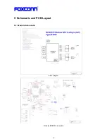
Page 13: ...13 5 Schematic and PCB Layout 5 1 Module Schematic Block Diagram Mckinley BB MAC Transceiver...
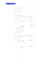
Page 14: ...14 RF Chain 0 RF Chain 1...
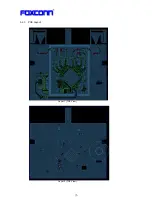
Page 16: ...16 5 2 3 PCB Layout Layer 1 TOP View Layer 2 TOP View...
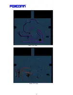
Page 17: ...17 Layer 3 TOP View Layer 4 TOP View...
Page 19: ...19 Antenna 0 2 4GHz radiation pattern Antenna 0 5GHz radiation pattern...
Page 20: ...20 Antenna 1 2 4GHz radiation pattern Antenna 1 5GHz radiation pattern...
Page 21: ...21 7 Module Mechanical Specifications Dimension W x L x H 40 0mmx37 5mmx5 45mm...
Page 23: ...23 9 Reliability Test Plan...
Page 24: ...24...
Page 26: ...26 11 Packing Information...
Page 27: ...27...

