Foxcom SatLight 7310D Installation And User Manual Download Page 24

7310D Installation and User’s Guide


Installation 

Foxcom Proprietary Information       

25 

Document No. 93-005-21-A1 

3.6  Aligning the Fiberoptic Cable 

The final step in installing the System 7310D is re-adjusting the Receiver Gain 
Control for unity gain.   

To set the unity gain

6

1.  Connect combiner output to input of Spectrum Analyzer (S.A.).  
2.  Set Signal Generator 1 to -3 dBm on the S.A. at 1000 MHz.  
3.  Repeat for S.G.2 at 1010 MHz. 
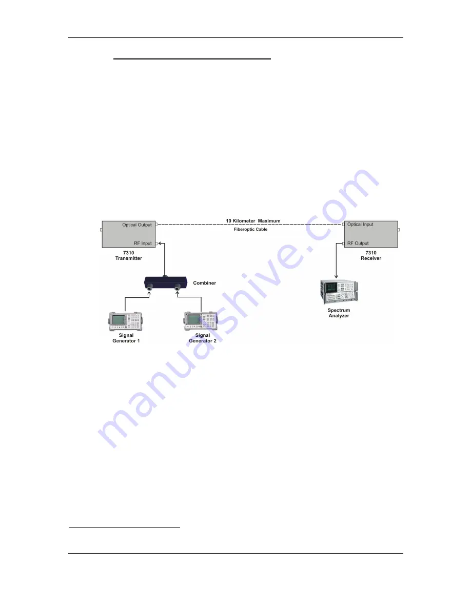
4.  Set up the system as shown in Figure 12. 
5.  Set the Transmitter Gain Control for 3

rd

 order intermodulation level of -40 dBc 

at the Receiver output. 
6.  Adjust the Receiver Gain Control for unity gain.   


Figure 12 - Fiberoptic Alignment Setup 


6

 If you are unable to perform this procedure refer to 

Manual Gain Control

, page 37. 

Summary of Contents for SatLight 7310D

Page 1: ...Copyright 2004 7310D Interfacility Link Installation and User s Guide...

Page 2: ...609 514 1800 Toll Free 1 866 ONEPATH Fax 609 514 1881 Foxcom Ltd Beck Science Center 8 Hartom Street Har Hotzvim P O Box 45092 Jerusalem 91450 Israel Tel 972 2 589 9888 Fax 972 2 589 9898 Website www...

Page 3: ...eceiver 20 3 4 Powering the IFL 21 3 5 Connecting the Back Panel Jumpers 22 3 6 Aligning the Fiberoptic Cable 25 4 Product Specifications 26 4 1 7310D IFL Specifications 26 4 2 Model Dimensions 28 4 3...

Page 4: ...eceiver Block Diagram 15 Figure 6 Typical Application of a 7310D Satellite Link 17 Figure 7 7180M Chassis Rear View 22 Figure 8 Jumper Installation Tx and Rx Only 23 Figure 9 Jumper Installation 2000...

Page 5: ...r Installation 2000 Switch in Slots 2 and 5 57 Figure 36 Unit Dimensions 58 Figure 37 7100M Chassis Dimensions 58 Figure 38 7310DT Transmitter Pinout 60 Figure 39 7310DR Receiver Pinout 62 Figure 40 7...

Page 6: ...nsmitter Pinout 29 Table 4 7310DR Receiver Pinout 31 Table 5 7180M Alarm Connector J12 Pinouts 34 Table 6 7180M Monitor Connector J13 Pinout 35 Table 7 Trouble Shooting 38 Table 8 2380 Alarms Pinouts...

Page 7: ...t that Foxcom proves to be defective This warranty does not apply to any product which has been subject to alteration abuse improper installation or application accident electrical or environmental ov...

Page 8: ...ES NO WARRANTY EXPRESSED OR IMPLIED WITH RESPECT TO ANY GOODS PARTS AND SERVICES PROVIDED IN CONNECTION WITH THIS AGREEMENT INCLUDING BUT NOT LIMITED TO THE IMPLIED WARRANTIES OF MERCHANTABILITY AND F...

Page 9: ...arrier immediately Notify Foxcom Networks as soon as possible Refer to Warranty and Repair Policy for further details Note Keep all packing material until you have completed the inspection 1 3 Certifi...

Page 10: ...ct please observe the following 1 Fuses The 7180M does not have fuses If the unit fails pull the power supply out from the chassis and then push it back in 2 The output of the receiver is AC coupled a...

Page 11: ...odulation formats can be transmitted i e QPSK FM etc The 7310D can be used in a wide variety of applications cellular PCS MMDS GPS VSAT CATV Earth Stations Broadcast Radar and others The RF signal is...

Page 12: ...f the 7310DT and the 7310DR units is a sticker3 which lists options 1 to 3 Under each option is a square If the unit includes a particular option the square under the option should be marked For examp...

Page 13: ...ion 14 Document No 93 005 21 A1 2 2 Product Drawings Figure 2 shows the front and rear panels of the 7310D Transmitter units Figure 2 7310D Transmitter Front and Rear Panels Figure 3 shows the front a...

Page 14: ...allation and User s Guide Introduction to the 7310D Foxcom Proprietary Information 15 Document No 93 005 21 A1 2 3 Block Diagrams Figure 4 7310DT Transmitter Block Diagram Figure 5 7310DR Receiver Blo...

Page 15: ...unit are LEDs The following tables describe the LEDs Table 1 7310DT Transmitter LEDs LED Name LED Function Laser Indicates if the optical output power control is functioning RF Indicates if the RF le...

Page 16: ...3 Setting up the receiver 4 Powering the IFL 5 Connecting the back panel jumpers 6 Aligning the fiberoptic cable Observe all warnings and cautions mentioned at the beginning of this manual page 11 If...

Page 17: ...13 pinouts 7180M Rackmount at pin 6 of the 9 pin connector standalone The power level should be 4 5 0 3 VDC 4 On the rear panel connect the coax cable to the RF Input Connector The RF LED should be li...

Page 18: ...ptic cable must be either fusion spliced or connected via FC APC connectors 2 Wipe the connector with a lint free cotton cloth 3 Note the polarity key of the optical connector before inserting To conn...

Page 19: ...ails regarding J13 pinouts 7180M Rackmount The voltage level should be 1V for each 1 mW measured at the Receiver input at pin 5 of the 9 pin connector standalone 4 On the rear panel connect the fibero...

Page 20: ...s The chassis can accept and power up to six units Note At temperatures below 10 C the Transmitter s internal heater will require an additional 100 mA The Transmitter s total power requirement will th...

Page 21: ...t selectors JP1 to JP4 The 3 pin selectors male are the connecting point between the slots and the back panel One pin is for the transmitter receiver Tx Rx one is for the optional 2000 1 1 Redundant S...

Page 22: ...0M has Tx or Rx units only place all jumpers on the lower two pins Figure 8 Jumper Installation Tx and Rx Only 3 If the 2000 Switch is installed in Slot 2 place the JP1 and JP2 jumpers on the higher t...

Page 23: ...ry Information 24 Document No 93 005 21 A1 Figure 10 Jumper Installation 2000 Switch in Slot 5 5 If the 2000 Switch is installed in Slots 2 and 5 place the JP1 JP2 JP3 and JP4 jumpers on the higher tw...

Page 24: ...6 1 Connect combiner output to input of Spectrum Analyzer S A 2 Set Signal Generator 1 to 3 dBm on the S A at 1000 MHz 3 Repeat for S G 2 at 1010 MHz 4 Set up the system as shown in Figure 12 5 Set th...

Page 25: ...ny 4 MHz BW 2 0 dB Typical 1 0 dB Typical 0 15 dB Typical Input Output Impedance 75 50 option Return Loss 13 dB Intermodulation Products7 40 dBc max Input Signal Range Total Power 8 20 to 0 dBm Output...

Page 26: ...Budget Distance 6 dB 15 km Optical Return Loss 50 dB Physical Specifications Chassis Capacity 8 Plug ins Chassis Size 19 x 5 25 x 7 3 Standalone Size 5 x 4 8 x 1 6 Power for Chassis 110 to 230 VAC Pow...

Page 27: ...7310D Installation and User s Guide Product Specifications Foxcom Proprietary Information 28 Document No 93 005 21 A1 4 2 Model Dimensions Figure 13 Unit Dimensions Figure 14 Chassis Dimensions...

Page 28: ...Indicates Laser Bias Range 4 5 0 3V 7 J12 P1 to J12 P8 J2 P1 P2 P3 P4 P5 P6 P7 P8 P9 P10 P11 P12 P13 P14 P15 P16 AGCA RF Alarm Open collector interface 10 Sinks current at low RF up to 30 mA 8 J12 P9...

Page 29: ...7310D Installation and User s Guide Product Specifications Foxcom Proprietary Information 30 Document No 93 005 21 A1 Figure 15 7310DT Transmitter Pinout...

Page 30: ...Spare Not Used 7 J12 P1to J12 P8 J2 P1 P2 P3 P4 P5 P6 P7 P8 P9 P10 P11 P12 P13 P14 P15 P16 AGCA RF Alarm Open collector interface12 Sinks current when RF level is low up to 30 mA 8 J12 P9 to J12 P16...

Page 31: ...ation and User s Guide Product Specifications Foxcom Proprietary Information 32 Document No 93 005 21 A1 Figure 16 7310DR Receiver Pinout CAUTION When monitoring the voltage outputs use a high resista...

Page 32: ...ne pin connector J11 Any monitor voltages to be measured may be done between the chassis ground and the required pin Figure 17 7180M Chassis Rear View Table 5 7180M Alarm Connector J12 Pinouts and Tab...

Page 33: ...3 3 4 RF AGC Alarm RfAlm4 4 5 RF AGC Alarm RfAlm5 5 6 RF AGC Alarm RfAlm6 6 7 RF AGC Alarm RfAlm7 7 8 RF AGC Alarm RfAlm8 8 9 Optical Alarm OptAlm1 1 10 Optical Alarm OptAlm2 2 11 Optical Alarm OptAlm...

Page 34: ...5 RSSI Monitor RSSI5 5 6 RSSI Monitor RSSI6 6 7 RSSI Monitor RSSI7 7 8 RSSI Monitor RSSI8 8 9 PDI Monitor PDI1 1 10 PDI Monitor PDI2 2 11 PDI Monitor PDI3 3 12 PDI Monitor PDI4 4 13 PDI Monitor PDI5...

Page 35: ...0 Switch provides optional 1 1 redundancy switching for all Foxcom Interfacility Links If the customer chooses to add redundancy switching to the link the pin connector jumpers need to be moved Detail...

Page 36: ...factory the only user adjustments are input and output RF signal levels accessible from the front panel and described in the following sections To adjust the Transmitter Gain 1 Set the input power to...

Page 37: ...gain with better airflow 3 If an optical power meter is available measure the optical power out of the transmitter The power should be more than 2 mW If an optical power meter is not available then us...

Page 38: ...r or another functioning receiver unit to verify optical power coming down the fiber 2 Optical power too low too many splits too long a distance thus exceeding optical budget System may still function...

Page 39: ...transmission Foxcom modules are sealed but dirt can occasionally enter during installation and alignment The input and output optical ports of all OnePath Networks equipment are known in the fiber op...

Page 40: ...Document No 93 005 21 A1 41 7 1 Cleaning Procedures for SC APC or FC APC Connectors Use a Kim Wipe to gently wipe the end face surface of the connector Alternatively a Cletop automatic connector clean...

Page 41: ...ure for SC APC or FC APC Bulkhead Ports CAUTION Clean the transmitter and receiver optical ports only when there is evidence of contamination or reduced performance 7 2 1 Swab Method Using a clean fib...

Page 42: ...pressed Air Method Using the extension tube of the compressed air blow into the port to remove any dust or debris Do not allow the tube to touch the bottom of the port Do not use commercial compressed...

Page 43: ...7310T STD or 7310R STD 1 Place the 7310D unit on the standalone flange matching the holes 2 Using four screws 4 or 6 secure the unit and the flange to the wall 3 Using the Foxcom Power Adapter apply...

Page 44: ...2380 Relay Adaptor is ordered separately from the 7180M chassis it must be mounted by the user The 2380 is easily mounted directly over the connectors on the 7180M backplane as shown below 9 1 Install...

Page 45: ...ptor Foxcom Proprietary Information Document No 93 005 21 A1 46 Figure 24 Mounting the Pins and Adaptor 5 Mount the four screws The screws must be installed in the order shown in Figure 25 and Figure...

Page 46: ...ry Information Document No 93 005 21 A1 47 CAUTION Use only the mounting screws provided by Foxcom Using other screws can permanently damage the unit Figure 27 Mounted 2380 6 Connect the cables 9 3 23...

Page 47: ...17 Name Slot Number 1 Alarm NOP1 1 2 Alarm COM1 1 3 Alarm NOP2 2 4 Alarm COM2 2 5 Alarm NOP3 3 6 Alarm COM3 3 7 Alarm NOP4 4 8 Alarm COM4 4 9 Alarm NOP5 5 10 Alarm COM5 5 11 Alarm NOP6 6 12 Alarm COM6...

Page 48: ...Monitor RSSI 5 6 RSSI Monitor RSSI 6 7 RSSI Monitor RSSI 7 8 RSSI Monitor RSSI 8 9 PDI Monitor PDI1 1 10 PDI Monitor PDI2 2 11 PDI Monitor PDI3 3 12 PDI Monitor PDI4 4 13 PDI Monitor PDI5 5 14 PDI Mon...

Page 49: ...output are DC coupled and can withstand the bias from a satellite receiver Do not exceed 25V DC bias 3 Do not allow any dirt or foreign material to get into the optical connector bulkheads This may ca...

Page 50: ...t 3 Using an optical power meter measure the optical power Insert the meter s cable into the Transmitter s optical connector Power levels should be higher than 2 mW pins J10 P13 through J10 P18 for th...

Page 51: ...fiber loss19 Alternatively use a DVM to measure the voltage at pins J10 P7 through J10 P12 for the slot being measured Refer to Table 13 on page 65 for details for details regarding J10 pinouts 7100M...

Page 52: ...uire an additional 120 mA The Transmitter s total power requirement will then be 390 mA CAUTION Ensure that there is a good airflow around the chassis rackmount Note By default the power supply is set...

Page 53: ...nd uptime the 7000S standby power supply can be optionally plugged in to the standard chassis The 7000S features hot swapping supplies may be installed and removed even during operation Each power sup...

Page 54: ...and the back panel One pin is for the Tx Rx one is for the 2000 RF Switch and one is for the 7100M A 2 pin jumper female is placed on the relevant pins to complete the connection between the 7100M an...

Page 55: ...d Rx Only 3 If the 2000 Switch is installed in Slot 2 place the JP1 and JP2 jumpers on the higher two pins and the JP3 and JP4 jumpers on the lower two pins Figure 33 Jumper Installation 2000 Switch i...

Page 56: ...prietary Information 57 Document No 93 005 21 A1 Figure 34 Jumper Installation 2000 Switch in Slot 5 5 If the 2000 Switch is installed in Slots 2 and 5 place the JP1 JP2 JP3 and JP4 jumpers on the hig...

Page 57: ...7310D IFL Installation and Users Guide Appendix IV 7100M Chassis Foxcom Proprietary Information 58 Document No 93 005 21 A1 Figure 36 Unit Dimensions Figure 37 7100M Chassis Dimensions...

Page 58: ...ignal Strength Indicator Range 0 2 10V 5 J10 P7 to J10 P12 J4 P7 to J4 P12 PDI Indicates Laser Optical Power Range 3 to 4V 6 J10 P13 to J10 P18 J4 P13 to J4 P18 LSRI Indicates Laser Bias Range 4 5 0 3...

Page 59: ...ation and Users Guide Appendix IV 7100M Chassis Foxcom Proprietary Information 60 Document No 93 005 21 A1 Figure 38 7310DT Transmitter Pinout CAUTION When monitoring the voltage outputs use only a hi...

Page 60: ...J4 P1 to J4 P6 RSSI RF Signal Strength Indicator Range 0 25 to 10V 5 J10 P7 to J10 P12 J4 P7 to J4 P12 PDI 1V mW Optical Power Received 6 Spare Not Used 7 J9 P1 to J9 P6 J2 P2 P5 P8 P11 P14 P17 AGC A...

Page 61: ...lation and Users Guide Appendix IV 7100M Chassis Foxcom Proprietary Information 62 Document No 93 005 21 A1 Figure 39 7310DR Receiver Pinout CAUTION When monitoring the voltage outputs use a high resi...

Page 62: ...at the backplane of the 7100M chassis The 7100M backplane incorporates 6 slots Pinouts from the nine pin connector at each slot are sent through the backplane assembly to the two 25 pin D connectors J...

Page 63: ...larm RFA2 2 3 RF Alarm RFA3 3 4 RF Alarm RFA4 4 5 RF Alarm RFA5 5 6 RF Alarm RFA6 6 7 8 9 10 11 12 13 14 Optical Alarm OPTA1 1 15 Optical Alarm OPTA2 2 16 Optical Alarm OPTA3 3 17 Optical Alarm OPTA4...

Page 64: ...SI Monitor RSSI2 2 3 RSSI Monitor RSSI3 3 4 RSSI Monitor RSSI4 4 5 RSSI Monitor RSSI5 5 6 RSSI Monitor RSSI6 6 7 PDI Monitor PDI1 1 8 PDI Monitor PDI2 2 9 PDI Monitor PDI3 3 10 PDI Monitor PDI4 4 11 P...

Page 65: ...2000 Switch provides optional 1 1 redundancy switching for all Foxcom Interfacility Links If the customer chooses to add redundancy switching to the link the pin connector jumpers need to be moved De...

Page 66: ...tor is ordered separately from the 7100M chassis it must be mounted by the user The 2300 is easily mounted directly over the connectors on the 7100M backplane as shown below 10 5 1 Installing the 2300...

Page 67: ...3 005 21 A1 Figure 42 Mounting the Pins and Adaptor 5 Mount the four screws The screws must be installed in the order shown in and Figure 44 Figure 43 Mounting the Screws 1 Figure 44 Mounting the Scre...

Page 68: ...Guide Appendix IV 7100M Chassis Foxcom Proprietary Information 69 Document No 93 005 21 A1 Figure 45 Mounted 2300 6 Connect the cables 10 5 3 2300 Dimensions and Front Panel Label Figure 46 2300 Dimen...

Page 69: ...ction Name Slot Number 1 Opt Alarm OPTA1 1 2 RF Alarm RFA1 1 3 Common COM1 1 4 Opt Alarm OPTA2 2 5 RF Alarm RFA2 2 6 Common COM2 2 7 Opt Alarm OPTA3 3 8 RF Alarm RFA3 3 9 Common COM3 3 10 Opt Alarm OP...

Page 70: ...SSI 2 3 RSSI Monitor RSSI 3 4 RSSI Monitor RSSI 4 5 RSSI Monitor RSSI 5 6 RSSI Monitor RSSI 6 7 PDI Monitor PDI1 1 8 PDI Monitor PDI2 2 9 PDI Monitor PDI3 3 10 PDI Monitor PDI4 4 11 PDI Monitor PDI5 5...

Page 71: ...all screwdriver under the Lip 4 Gently press upwards the Fuse Drawer will come out slightly Figure 49 Fuse Drawer 230 Figure 50 Voltage Selector 230 Side 5 Pull the Fuse Drawer out completely the Volt...

Page 72: ...replace the fuse use the parts specified in the following table Table 16 AC Voltage Fuse Part Numbers27 Voltage Current Littelfuse Part No Schurter Part No 230 0 5 A 239 500 0034 3114 115 1 0 A 239 0...

Page 73: ...ormation Foxcom Proprietary Information 74 Document No 93 005 21 A1 11 Appendix V Pinouts Detailed Information The following charts give detailed information regarding the chassis and 2000 Switch pino...

Page 74: ...7310D IFL Installation and Users Guide Appendix V Pinouts Detailed Information Foxcom Proprietary Information 75 Document No 93 005 21 A1 Figure 53 7180M with 2000 Switch Pinout...

Page 75: ...Guide Appendix V Pinouts Detailed Information Foxcom Proprietary Information 76 Document No 93 005 21 A1 Figure 54 Pinout of 7180M Jumper with 2000 Switch in Slot 2 and 5 Figure 55 Pinout of 7180M Jum...

Page 76: ...User s Guide Appendix V Pinouts Detailed Information Foxcom Proprietary Information 77 Document No 93 005 21 A1 Figure 56 Pinout of 7180M Jumper with 2000 Switch in Slot 5 Figure 57 Pinout of 7180M Ju...

Reviews: