background image


F8L10GW LoRa Gateway


  Page  26  of  37 


Add

11th Floor, A-06 Area, No.370, Chengyi Street, Jimei, Xiamen, Fujian, China. 

http://www.four-faith.com 


Tel:+86-592-6307217           Fax: +86-592-5912735


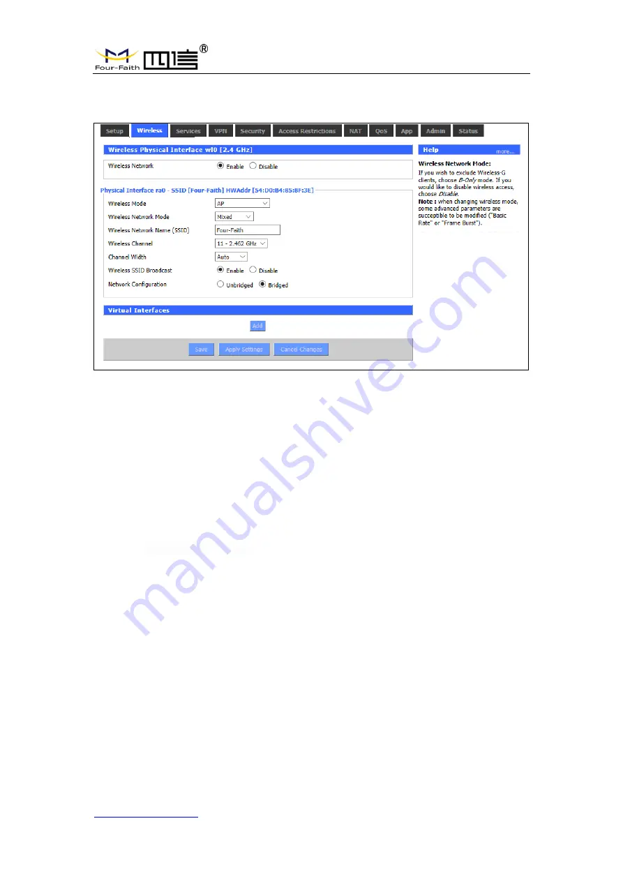
3.3.2.1 Basic Configuration 


Enable: 

Turn on WIFI

Disable:

 Turn off WIFI.


Wireless mode:

 AP, client, ad-hoc, relay and relay bridge are available. 

Wireless network mode: 


Hybrid: Support wireless devices with 802.11b/g/n standards at the same time


Bg-mix: Support both 802.11b and 802.11g standards wireless devices.


B Only: 

Only 802.11b standard wireless devices are supported. 

G Only: 

Only 802.11g standard wireless devices are supported.


NG-mix: 

It supports 802.11g and 802.11n wireless devices. 

Only N: 

Only 802.11n standard wireless devices are supported.


8021.11n  transmission  mode: 

When  the  wireless  network  mode  is  "only  N",  select  its 

transmission modes:


Greenbelt

: When sure that no other 802.11a/b/g device in the surrounding environment 

using the same channel, using this mode or increasing throughput. If there are 

other 802.11a/b/g devices in the environment that using the same channel, the 

messages you send can be errors, re-sends, and so on. 

Mixture

This model  is  the  opposite  of  the  greenbelt model,  but  it  reduces  throughput.


Wireless network name (SSID)

:

 The network name Shared by all devices in a wireless 

                                                    network, and the SSID of all devices is the same.SSID 

consists  of  Numbers  and  letters,  case  -  sensitive,  no 

more than 32 characters. 

Wireless  channels

:  there  are  1-13  channels  available.  In  the  environment  of  multiple 

wireless devices, please try to avoid using the same channels as 

other devices. 

Summary of Contents for F8L10GW

Page 1: ...F8L10GW LoRa Gateway User Manual FCC ID 2ALUW F8L10GW ...

Page 2: ...men Fujian China http www four faith com Tel 86 592 6307217 Fax 86 592 5912735 Files Revised Record Date Version Remark Author 2018 07 19 V1 0 0 Initial version Cheney Carolin 2018 10 11 V1 0 1 Add 1 3 system block diagram Modify document format Document style adjust Font size adjustment Jim ...

Page 3: ...mission all commercial use of the files from Four Faith are forbidden such as copy distribute reproduce the files etc but non commercial purpose downloaded or printed by individual all files shall be not revised and the copyright and other proprietorship notice shall be reserved are welcome Trademark Notice Four Faith 四信 are all registered trademarks of Xiamen Four Faith Communication Technology C...

Page 4: ...dd 11th Floor A 06 Area No 370 Chengyi Street Jimei Xiamen Fujian China http www four faith com Tel 86 592 6307217 Fax 86 592 5912735 Pole mounted Installation Wall mounted Installation Note Accessories are subject to the purchased model ...

Page 5: ... 11 2 3 Installation 12 2 3 1 SIM UIM Installation 12 2 3 2 Wall mounted Installation 13 2 3 3 Pole mounted Installation 16 2 3 4 Antenna Installation 17 2 4 Indicator light description 18 Chapter 3 Configuration 20 3 1 Configuration Connection 20 3 2 Access to Configuration Web Page 20 3 2 1 IP Address Setting 20 3 2 2 Login configuration web page 21 3 3 Management Configuration 23 3 3 1 Connecti...

Page 6: ...terminal data to the cloud through 3G 4G or wired Ethernet Support WiFi wireless configuration management and online upgrade GPS positioning AC power supply F8L10GW is complied with standard LoRaWAN protocol it s compatible with LoRaWAN devices and NS The product has been widely used in M2M industry smart grid smart transportation industrial automation intelligent buildings fire control public sec...

Page 7: ...annel LoRaWAN RF base station chip Aluminum housing IP65 rated Support AC Power supply Stability and Reliability WDT watchdog design Complete anti drop mechanism ensures data terminal always online Built in 1 5 KV electromagnetic isolation protection in Ethernet interface Built in 15KV ESD protection in SIM UIM card interface Built in reverse phase protection over voltage protection and lightning ...

Page 8: ...eiving different frequency same frequency Positioning function GPS Network connectivity 3G 4G Ethernet Management WiFi wireless management and upgrade TF card local storage supported Operating temperature 35 50 Dimensions 289 4 223 62 115 mm IP65 rated Power supply 100 240V 50 60Hz 0 8A Electrical Performance No Parameter Technical Data 1 Rated input voltage 100 240V AC 2 Rated output voltage 12V ...

Page 9: ...nect device of Power Supply Environmental Limits Item Content Operating Temperature 35 50º C Note 1 Do not use the products in the environment at too high or too low temperature The suitable temperature for the product and accessories is 35 50 Antenna Specification Item Content LoRa antenna N type female Omni Directional FRP Antenna 2dBi gain GPS antenna N type female Omni Directional FRP Antenna ...

Page 10: ...is equipment has been tested and found to comply with the limits for a Class B digital device pursuant to part 15 of the FCC Rules These limits are designed to provide reasonable protection against harmful interference in a residential installation This equipment generates uses and can radiate radio frequency energy and if not installed and used in accordance with the instructions may cause harmfu...

Page 11: ...power interface antenna interface 2 2 Packing List 2 2 1 Wall mounted Packing List Item Qty Remark F8L10GW LoRa Gateway 1 4G Omni Directional FRP Antenna 1 Optional WIFI Omni Directional FRP Antenna 1 GPS Omni Directional FRP Antenna 1 LoRa Omni Directional FRP Antenna 1 Bracket 1 Swelling screw ø14mm 3 Wire 1 Optional User manual CD 1 Optional QC passed card 1 Warranty card 1 2 2 2 Pole mounted P...

Page 12: ...d card 1 Warranty card 1 2 3 Installation F8L10GW Dimensions 2 3 1 SIM UIM Installation 1 Cut off the power 2 Unscrew the M6 screws figure 2 3 1 as below 3 Insert SIM UIM card figure 2 3 2 as below 4 Push the SIM UIM card and the card will pop up automatically 5 Tighten M6 screws Warning 1 Power must be off before installing SIM UIM card 2 M6 screws must be tightened and fixed ...

Page 13: ...3 2 Insert SIM UIM card 2 3 2 Wall mounted Installation Step 1 The wall where the gateway is installed must be flat and open sided make sure no shield within 5 meters around LoRa antenna Drill 3 holes of ø14mm diameter 60 mm depth swelling screw is about 50mm long according to the position of the bracket mounting holes Figure 2 3 3 Note Press the shelf against the wall mark it and then punch the h...

Page 14: ...men Fujian China http www four faith com Tel 86 592 6307217 Fax 86 592 5912735 Figure 2 3 3 Hole Location Diagram Step 2 Fix the swelling screws in the bracket Figure 2 3 4 Figure 2 3 4 Swelling Screws Installation Diagram Step 3 Fix the bracket on the wall and tighten the screw Figure 2 3 5 ...

Page 15: ...ea No 370 Chengyi Street Jimei Xiamen Fujian China http www four faith com Tel 86 592 6307217 Fax 86 592 5912735 Figure 2 3 5 Bracket Installation Diagram Step 4 Tighten the four screws and fix the gateway on the bracket then install the antenna Figure 2 3 6 ...

Page 16: ...na http www four faith com Tel 86 592 6307217 Fax 86 592 5912735 Figure 2 3 6 Fix Four Screws Diagram 2 3 3 Pole mounted Installation Step 1 Prepare a pole with 70 90mm diameter make sure no shield within 5 meters around LoRa antenna Step 2 Put the clamp into the pole fix the clamp in the pole with screws ...

Page 17: ...ote Pole is not included in the product 2 3 4 Antenna Installation After gateway is installed on the wall or pole connect the Matching antennas to the antenna interface Make sure the antennas are tightened to get best signal Fig 2 3 7 Note Each antenna must install to the right interface and Using a tool to tighten otherwise the gateway won t work properly and waterproof ...

Page 18: ...iption The F8L10GW offers the following indicators Power System Online SIM LoRa WAN WIFI Signal Strength Status description of each indicator are as below Indicator light Status Description PWR Red light on Power on Red light off Power off SYS Yellow light flash System work properly Yellow light off System work improperly WIFI Blue light on WIFI on Blue light off WIFI off LoRa Green light on LoRa ...

Page 19: ...el 86 592 6307217 Fax 86 592 5912735 Green light off LoRa abnormal Green light flash Data Transmitting 3G 4G Signal Turn on an light Weak signal strength less than 90db Turn on two lights Medium signal strength 70db 90db Turn on three lights Better signal strength greater than 70db Online Green light off Online Green light on Offline ...

Page 20: ...work cable one end is connected to any Ethernet interface of F8L10GW Local Network LAN port and the other end is connected to the Ethernet interface of PC When connect with WIFI the default SSID of F8L10GW is FOUR FAITH without password verification 3 2 Access to Configuration Web Page 3 2 1 IP Address Setting Specify IP address Set the IP address of PC as 192 168 1 9 or other IP address of 192 16...

Page 21: ... VPN Security Access Restrictions NAT QoS Settings Applications Management and Status Users enable to browse slave pages by click one main page This manual introduces the parameters related to F8L10GW other parameters can be default To access F8L10GW web based Web management tool enter the default IP address 192 168 1 1 of the F8L10GW in the address bar of browser press enter When login the web pa...

Page 22: ...ina http www four faith com Tel 86 592 6307217 Fax 86 592 5912735 Then access to main page Users need to enter user name and password if it is the first time to login Enter username and password to access the web page default username and password are both admin You can change the username and password on ...

Page 23: ...on t take effect click Apply button to make settings to take effect or click Cancel button to cancel the settings Basic Settings WAN Connection Type setting section describes how to configure F8L10GW to connect to the Internet Details on this can be obtained from your ISP WAN Connection Type Select the Internet connection type provided by your ISP from the drop down menu WAN connection type includ...

Page 24: ...nnection is finished Mode 2 DHCP 4G The IP address of the WAN port is obtained by dhcp 4G Keep Online This function is to detect whether the Internet connection is active If users set it the F8L10GW will automatically detect the Internet connection Once gateway detects the link disconnected or invalid the system will automatically reconnect and re establish the effective connection If network is b...

Page 25: ...y Detection Interval time interval between two detection unit is second Primary Detection Server IP Primary server IP used to response gateway s detection packet This item is only valid for Ping and Route Backup Detection Server IP Backup server IP used to response gateway s detection packet This item is only valid for Ping and Route STP STP Spanning Tree Protocol can be applied to the loop networ...

Page 26: ...dard wireless devices are supported 8021 11n transmission mode When the wireless network mode is only N select its transmission modes Greenbelt When sure that no other 802 11a b g device in the surrounding environment using the same channel using this mode or increasing throughput If there are other 802 11a b g devices in the environment that using the same channel the messages you send can be err...

Page 27: ... no bridge is connected to F8L10GW and the IP address needs to be manually configured Virtual interface Click to add a virtual interface after successfully addition click to remove the virtual interface AP independence completely isolate all wireless client devices so that they can only access a fixed network with AP connections Note save settings save your changes after changing the mode of wirel...

Page 28: ...nd the default value is 1700 Server downstream port LoRaWAN data service center program downlink port The range is 0 65535 and the default value is 1700 Advanced configuration of LoRa Gateway LoRa Gateway ID the unique identity of the LoRa Gateway through which the server can distinguish different LoRa Gateway CRC validation ok Turn on off CRC for validation Default is on CRC validation error Turn...

Page 29: ...and use it Web Access This feature allows you to manage F8L10GW using either the HTTP protocol or the HTTPS protocol If you choose to disable this feature you will need to reboot manually You can also activate or disable the F8L10GW information page That way you can use a password to protect the page enter the correct username and password Protocols protocols support web pages include HTTP and HTT...

Page 30: ...esents F8L10GW Internet IP address 8080 on behalf of the specified port in your web browser address bar You will be requested to enter the F8L10GW password If you are using HTTPS you need to specify the URL to https xxx xxx xxx xxx 8080 not all firmware support the reconstruction of the SSL SSH management you can enable SSH to secure remote access to F8L10GW Note that to understand the setup of th...

Page 31: ...F8L10GW can be monitored and managed parameter configuration WIFI advertising update through the customized remote management server 3 3 4 2 The factory default To clear all configurations and restore to factory default values click Yes button and save All the Settings will lose when revert to the default Settings The default configuration for this feature is No For more information click More ...

Page 32: ...ess there is useful functionality in new version Note Upgrading of F8L10GW firmware may lose the configuration Settings It is essential to back up the setup information of F8L10GW before upgrading After the refresh reset to Click Default Settings to reset the default Settings of the firmware version of F8L10GW after the upgrade Click browse select the upgrading firmware file and then click the Upg...

Page 33: ...l 86 592 6307217 Fax 86 592 5912735 To backup the F8L10GW configuration file click the Backup button After that follow the instructions on the screen To restore the F8L10GW configuration file click the Browse button After finding the backup file follow the instructions on the screen Select the backup file and click the Restore button ...

Page 34: ...f 37 Add 11th Floor A 06 Area No 370 Chengyi Street Jimei Xiamen Fujian China http www four faith com Tel 86 592 6307217 Fax 86 592 5912735 3 3 5 State 3 3 5 1 F8L10GW Server status connection status to the specified LoRaWAN server ...

Page 35: ...Street Jimei Xiamen Fujian China http www four faith com Tel 86 592 6307217 Fax 86 592 5912735 Mac Mac address of F8L10GW LoRaWAN server identification code of different F8L10GW GPS status it is GPS signal status indicator Longitude dimension and altitude are obtained from GPS ...

Page 36: ... describe how to make F8L10GW Gateway enter configure state with the Windows XP Hyper Terminal 1 Press Start Programs Accessories Communications Hyper Terminal 2 Enter the connection name and select OK 3 Select the actual physical serial port of PC that is used to connect to the F8L10GW Console port and select OK 4 Configure the super terminal as shown below and select OK Communication rate 115200...

Page 37: ...ttp www four faith com Tel 86 592 6307217 Fax 86 592 5912735 Data bit 8 Parity check none Stop bit 1 Data flow control none At this point the super terminal is running normally If you are using win7 you can download a win7 super terminal online Or other common serial interactive software the use way is similar ...

Reviews: