background image

When power is provided to these heaters the 

heater elements will take several minutes to 

achieve full infrared output that can be confirmed 

by an orange to dull red glow on the element 

surface. The element under this condition is 

operating between 1,500 and 1,600° F emitting 

medium wavelength (approx. 3 microns or 

millionths of a meter) infrared energy.  This 

energy, that can also be considered “radiation” is 

not harmful, yet is very effective at heating 

objects and surfaces that are within the 

line-of-sight of the elements and the heater’s 

reflective surfaces.

When power is provided or removed from these 

heaters, you may hear unfamiliar sounds that are 

caused by the expansion and contraction of metal 

components in the heater.  This is normal.

Pre-Season Maintenance and Annual Inspection

To ensure your safety and years of trouble-free operation from the heaters, periodic service and  

inspections must be done by a trained maintenance person or licensed electrician.

To obtain maximum performance from your heater(s) each year, we recommend the following be 

performed at the start of the heating season: 

1.  Disconnect power to heater at main panel. Be sure that heating elements have cooled down.

2.  Clean housing surfaces with a damp cloth.

3.  Blow or dust off the element.

4.  Repair or replace damaged power cables.

5.  DO NOT hose-down these heaters.

ISSUE DATE 07-2015     REV. DATE ------------     REV. LEVEL: -       ECO 1-7090        OIPM P/N 8419                     PG 11 OF12

OPERATION

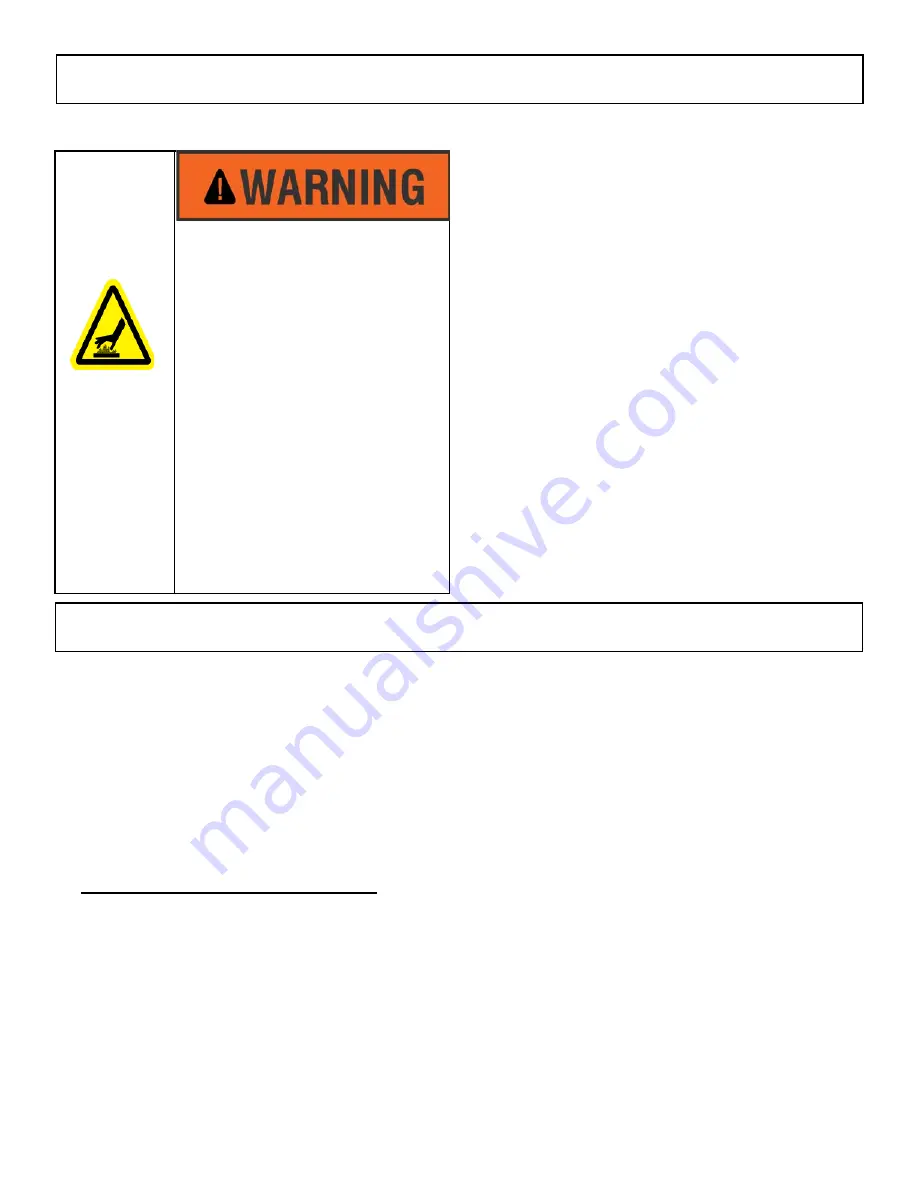
BURN HAZARD

•  Serious injury or death may 

occur.

•  Allow heater to fully cool after 

power is removed (may take 

minutes) before touching or 

working on it.

MAINTENANCE

Summary of Contents for FSS Series

Page 1: ...E REV LEVEL ECO 1 7090 OIPM P N 8419 PG 1 OF12 TPI Corporation P O Box 4973 Johnson City TN 37602 www tpicorp com FSS Series Heavy Duty Flat panel Emitter Electric Overhead Infrared Heaters IMPORTANT SAFETY INFORMATION INSIDE Serious injury or death possible Read understand and follow all safety information and instructions in this manual before using or servicing this product Retain these instruc...

Page 2: ...r inspected by a reputable electrician before reusing 5 Do not use outdoors 6 To disconnect heater turn controls to off and turn off power to heater circuit at the main disconnect panel or operate internal disconnect switch if provided 7 Do not insert or allow foreign objects to enter any ventilation or exhaust opening as this may cause an electric shock or fire or damage to the heater 8 To preven...

Page 3: ...rt symbol indicates a potentially hazardous situation which if not avoided may result in property damage As defined in ANSI Z535 4 2002 Thank you very much for selecting Fostoria s overhead electric infrared heating equipment for your comfort heating needs These products were engineered with the most reliable components and materials available and are equipped with features to assure ease of insta...

Page 4: ...D CLEARANCES DO NOT install closer than 36 inches to a vertical surface or 24 inches to a ceiling Heaters MUST BE SEPARATED by more than 36 inches and 72 inches from any combustible surface in direct radiation path 87 inches for FSS 95 Series EXPLOSION HAZARD FIRE HAZARD BURN HAZARD Serious injury or death may occur Not for residential use Do not use outdoors Use for comfort heating only Do not us...

Page 5: ...120 1ph 15 14 N A 1 3150 10 748 Yes Yes FSS 3124 1 240 1ph 13 13 N A Yes Yes FSS 3127 1 277 1ph 11 37 N A Yes Yes FSS 3148 1 480 1ph 6 56 N A Yes Yes FSS 3157 1 600 1ph 5 48 N A Yes Yes FSS 4320 3 208 1 or 3ph 20 67 11 94 1 4300 14 672 Yes Yes FSS 4324 3 240 1 or 3ph 17 91 10 36 Yes Yes FSS 4327 1 277 1ph 15 52 N A Yes Yes FSS 4348 3 480 1 or 3ph 8 96 5 18 Yes Yes FSS 4357 3 600 1 or 3ph 7 48 4 32...

Page 6: ...E 07 2015 REV DATE REV LEVEL ECO 1 7090 OIPM P N 8419 PG 6 OF12 Model Series Dimension A inches Dimension B inches Dimension C inches Weight lbs FSS 14 8 1 2 9 26 7 FSS 31 8 1 2 9 46 13 FSS 43 9 3 4 20 29 18 FSS 95 7 3 4 20 49 31 SPECIFICATIONS con t ...

Page 7: ...hat is workmanlike and compliant with all applicable codes Preparations For Hanging Heaters Hardware to suspend these heaters from overhead supports chain S hooks etc is not included with the product Make certain that the hardware to be used is capable of supporting at least twice the total weight of the heater s in question Refer to the specifications section of this manual for product weights Id...

Page 8: ...be EVEN WITH or LOWER THAN the horizontal plane of the heater housing ISSUE DATE 07 2015 REV DATE REV LEVEL ECO 1 7090 OIPM P N 8419 PG 8 OF12 FIRE HAZARD BURN HAZARD Install heaters to comply with REQUIRED CLEARANCES listed above at right Do not mount heaters vertically INSTALLATION HANGING HEATERS INSTALLATION PLANNING CON T Heater Model kW Volts Amps Recommended AWG Wire Size 3ph 1ph 3ph 1ph FS...

Page 9: ...TE 07 2015 REV DATE REV LEVEL ECO 1 7090 OIPM P N 8419 PG 9 OF12 SERIES RECOMMENDED MOUNTING HEIGHTS FSS 14 8 10 Ft FSS 31 8 12 Ft FSS 43 10 14Ft FSS 95 12 16Ft Mounting Centers In Inches Series Dim A Dim B FSS 14 14 1 4 2 1 2 FSS 31 34 1 4 2 1 2 FSS 43 18 1 4 12 3 4 FSS 95 36 3 4 12 3 4 ...

Page 10: ... 1 can be wired for single phase or three phase applications See wiring diagrams on page 10 2 Remove the cover from the terminal box 3 Connect the lead wires to the 90 C rated sup ply wiring routed into the splice box with wire nuts or other safe mechanical means Black and white supply leads can be connected to either element lead wire Be sure green lead from supply and green bonding lead from the...

Page 11: ...on of metal components in the heater This is normal Pre Season Maintenance and Annual Inspection To ensure your safety and years of trouble free operation from the heaters periodic service and inspections must be done by a trained maintenance person or licensed electrician To obtain maximum performance from your heater s each year we recommend the following be performed at the start of the heating...

Page 12: ...L ECO 1 7090 OIPM P N 8419 PG 12 OF12 1 2 3 4 FOR 3PH OPERATION L1 1 4 L2 2 L3 3 FOR 1PH OPERATION L1 1 3 L2 N 2 4 WIRING SCHEMATIC L1 L2 N FOR FSS 14 FSS 31 FSS 4327 1 AND FSS 9527 1 MODELS FOR ALL OTHER MODELS INSTALLATION WIRING con t ...

Reviews: