background image

91

Advanced Operations

OFF

ON

MIDI

OUTPUT

INPUT

OUTPUT

INPUT

POWER

PHANTOM

S/P DIF / DATA

DIGITAL MULTITRACKER

LOCATE ABS 0

LOCATE REC END

SEL

TIMEBASE

CURSOR

PHANTOM

ACCESS

PEAK

CH ON/OFF

L

R

GUITAR

GUITAR

LINE

MIC

LINE

MIC

MIN

MAX

MASTERING

TRAINING

EFFECT

EQ

PAN

SCENE SEQ.

SCENE

TRACK

UNDO

SETUP

PUNCH

AUTO

LOOP

PITCH

SCRUB

VARI

F FWD

REWIND

PLAY

STOP

RECORD

EXIT

ENTER

TRIM

TRIM

WAVE FORM

MIX PARAMETER

PGM

FADER

MAP

ON/OFF

2TRK MODE

F1

F2

F3

SHIFT

EDIT

EDIT

EDIT

MARK

DELETE

LOCATE

FOOT SW

ST OUT

PHONES

INPUT A

BOUNCE

INPUT B

+6

-10

-20

-40

-

-30

0

+6

-10

-20

-40

-

-30

0

+6

-10

-20

-40

-

-30

0

+6

-10

-20

-40

-

-30

0

+6

-10

-20

-40

-

-30

0

+6

-10

-20

-40

-

-30

0

+6

-10

-20

-40

-

-30

0

+6

-10

-20

-40

-

-30

0

PEAK

CH ON/OFF

2

3

4

5

6

7/8 2TRK

1

MASTER

TRACK STATUS / TRACK SEL

TRACK STATUS

RED

REC

GREEN

PLAY

OFF

MUTE

STATUS

/SEL

EJECT

    /YES

  /NO

SHUTTLE

JOG

UNBAL

UNBAL

BAL

BAL

F1

F2

F3

EDIT

/REDO

REC EFF

ST OUT L, R

MIDI IN

MIDI OUT

MIDI IN

MIDI Sound Source

MIDI Sequencer

MIDI OUT

Master Recorder

MIDI clock & song position ponter

INPUT

1

2

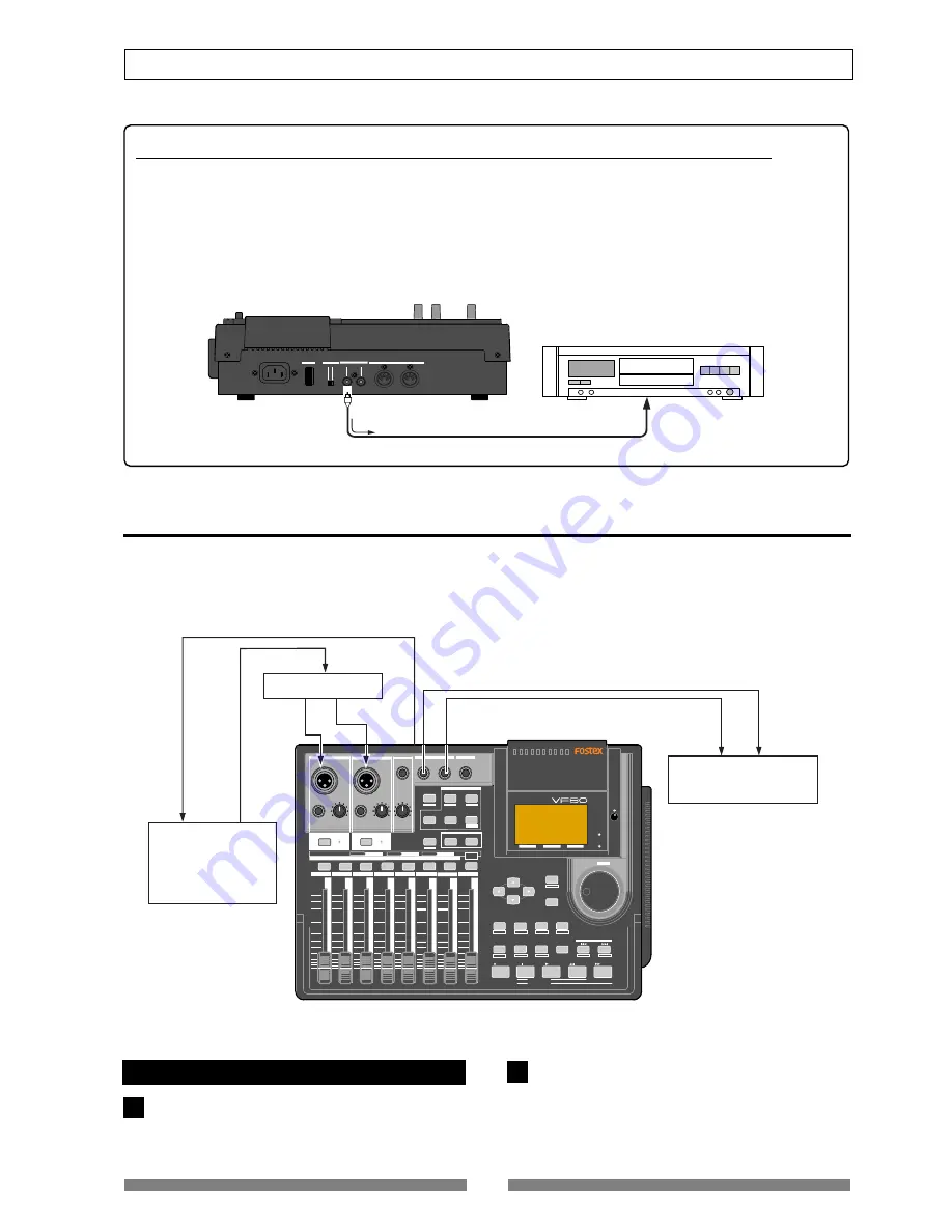
Recording the VF80 stereo output signals digitally onto an external digital device

You can record the stereo output signal digitally onto an external digital device via the 

[S/P DIF/DATA OUTPUT]

connector.

You do not have to carry out any special operation for outputting an S/P DIF digital signal from the 

[S/P DIF/

DATA OUTPUT]

 connector, because it is always output there.

All you have to do for mixing down to an external digital device digitally is to connect the device to the 

[S/

P DIF/DATA OUTPUT]

 connector. You can perform the digital mixdown during the mixdown process described

in "

Mixdown

" of the "

Basic recording/playback

" chapter as well as in the mastering mode described in "

Master-

ing mode

" of this chapter.

MIDI clock sync system

By setting any desired meter at any desired point of the programmable tempo map contained in the VF80, and
by output of a MIDI clock and song position pointer according to the setting, a hardware type MIDI sequencer
can be synchronized as a MIDI clock slave.  Consequently, in this system, the VF80 will be the master and the MIDI
sequencer the slave.

Connecting external equipment

Connect the VF80 MIDI OUT to MIDI IN of the MIDI
sequencer.

Set the MIDI sequencer for “external sync mode
(EXTERNAL SYNC) by MIDI clock.”

Refer to the Owners Manual of the equipment in use
for details.

Summary of Contents for VF80

Page 1: ...IND PLAY STOP RECORD EXIT ENTER TRIM TRIM WAVE FORM MIX PARAMETER PGM FADER MAP ON OFF 2TRK MODE F1 F2 F3 SHIFT EDIT EDIT EDIT MARK DELETE LOCATE FOOT SW ST OUT PHONES INPUT A BOUNCE INPUT B 6 10 20 40 30 0 6 10 20 40 30 0 6 10 20 40 30 0 6 10 20 40 30 0 6 10 20 40 30 0 6 10 20 40 30 0 6 10 20 40 30 0 6 10 20 40 30 0 PEAK CH ON OFF 2 3 4 5 6 7 8 2TRK 1 MASTER TRACK STATUS TRACK SEL TRACK STATUS RE...

Page 2: ... within an equilateral triangle is intended to alert the user to the presence of uninsulated dangerous voltage within the product s enclosure that may be of sufficient magnitude to constitute a risk of electric shock to persons The exclamation point within an equilateral triangle is intended to alert the user to the presence of important operating and maintenance servicing instructions in the lite...

Page 3: ...plete packaging or caused during transport It is prohibited by law to use any part of a CD recording or video images or audio data for which copyright is possessed by a third party for commercial purposes such as contents broadcasts sales or distribution any purpose other than for your personal pleasure Fostex is not responsible for any direct damage or indirect damage caused by using the VF80 Not...

Page 4: ... song data Please read page 96 I want to use a condenser microphone Please read page 27 I want to equalize the sound Please read pages 36 and 40 I want to delete a program Please read page 62 I want to locate the desired position Please read pages 32 and 59 I want to format a hard disk Please read page 20 I want to mixdown tracks to an external master recorder Please read pages 38 and 76 I want to...

Page 5: ... want to save song data to a DAT Please read page 97 I want to make a tempo map Please read pages 122 and 124 I want to mixdown tracks without using an external master recorder Please read page 79 I want to set the MTC offset time Please read page 127 I want to synchronize theVF80 with an external device Please read page 91 I want to feed the MIDI sync signal to an external MIDI device Please read...

Page 6: ...single track 28 Preparation for recording 28 Contents Recording 29 Playback 29 Basic recording recording onto two track 30 Preparation for recording 30 Recording 31 Playback 31 Mark function 32 Setting a mark on the fly 32 Locating a mark 32 Deleting a mark 32 ABS Locate 33 Punch In Out 33 Manual punch in out using the keys on the unit 33 Punch in out using the Foot Switch 33 Auto punch in out fun...

Page 7: ...unce mode 73 Setting pan position 73 Setting level of each track 73 Performing the track bounce 73 Training mode 74 Connecting the instrument and headphones 74 On Off of training mode 74 Slowing down the playback speed 75 Changing the pitch 75 Canceling the center positioned sound 75 Setting the cancel position 75 Boosting the bass sound 75 Playing along with the playback sound 75 Mastering mode 7...

Page 8: ...nter the SETUP mode 122 Time Signature Setting 122 New Registering of Time Signature 122 Correcting the Registered Time Signature 122 Deleting of Time Signature 122 Clearing All Time Signature data 122 Changing the Bar Offset Figure 122 Setting aTempo 124 New Registering of Tempo 124 Correction of the Registered Tempo 124 Erasing of the Registered Tempo 124 Setting the Metronome function 125 Setti...

Page 9: ...ument by slowing down playback shifting the pitch of the recorded performance or masking the solo instrument voice Scene memory function allows you to save and load up to 99 mixer scenes including fader positions and EQ effect settings You can feed the mixed down signal from the S PDIF output connector to an external digital device such as a DAT recorder for digital recording The Internal Masterin...

Page 10: ...title with its program number appears at the top left of the normal screen as shown below The remain indicator shows how much recording time is left on the current hard disk The VF80 program is managed by a 24 hour time counter however the actual recording time left de pends on the available disk space The remain indicator appears on the LCD during re cording or on REC standby showing the rough re...

Page 11: ...re called events With the VF80 you can create up to 512 events per track You cannot make any further recording when 512 events are created In the normal use 512 events are enough The VF80 can show the current number of events on the LCD It also shows a warning message if you are going to make recording when 512 events already exist You may resolve this problem by saving the program see Save Load o...

Page 12: ...default setting however you can change to set it between bar 9 and bar 2 MTC MIDI Time Code runs in sync with the ABS time The MTC value h m s corresponding to ABS 0 can be set which is called MTC offset If you set the MTC offset to 01h 00m 00s the MTC will start from 01h 00m 00s and at the ABS 00h 00m 00s position the MTC value will be 02h 00m 00s The example below shows that the current position...

Page 13: ...UB VARI F FWD REWIND PLAY STOP RECORD EXIT ENTER TRIM TRIM WAVE FORM MIX PARAMETER PGM FADER MAP ON OFF 2TRK MODE F1 F2 F3 SHIFT EDIT EDIT EDIT MARK DELETE LOCATE FOOT SW ST OUT PHONES INPUT A BOUNCE INPUT B 6 10 20 40 30 0 6 10 20 40 30 0 6 10 20 40 30 0 6 10 20 40 30 0 6 10 20 40 30 0 6 10 20 40 30 0 6 10 20 40 30 0 6 10 20 40 30 0 PEAK CH ON OFF 2 3 4 5 6 7 8 2TRK 1 MASTER TRACK STATUS TRACK SE...

Page 14: ... to the signal from INPUT B You can adjust the gain to accept input signals between 50 dBV MIC and 2 dBV LINE 7 PHONES Headphones knob Adjusts the level of headphones for monitoring 8 PHONES Headphones connector Connects headphones for monitoring Connector type TRS phone jack 9 ST OUT L R Stereo out connector Outputs the stereo L and R buss signal Connects to a master recorder etc Reference output...

Page 15: ...ack status among OFF PLAY and REC READY During playback pressing the key switches between OFF and PLAY During recording you cannot change the track status When you view or edit mixer parameters such as pan and EQ in the Mix parameter edit mode described later you can select the target track by pressing the corresponding TRACK STATUS TRACK SEL key The illumination of each key shows the track status...

Page 16: ... MODE MASTERING key Turns on or off the Mastering mode in which tracks 7 8 are played back with sound processing the EQ reverb and compressor When the mode is active the key lights up 22 STATUS SEL MASTER key Turns on or off the master channel Also used to select the track for the mix parameter edit 23 MASTER fader Adjusts the output levels of the stereo L R busses 24 Track faders Adjusts the play...

Page 17: ... the previous mark point Pressing this key while holding down the SHIFT key stores the current position in the mark map 36 LOCATE DELETE key Each press of this key locates the next mark point Pressing this key while holding down the SHIFT key delete the current mark point directly 37 F FWD key Pressing this key while stopped fast forwards the position at 30x speed Pressing this key during playback...

Page 18: ...hile holding down the SHIFT key makes you ready to edit the auto punch parameters In point and Out point via the screen 46 TIME BASE SEL F2 key Pressing this key switches the time base shown on the screen among the following a ABS absolute time Absolute time from 00h00m00s to 23h59m59s b Bar Beat Clk Bar Beat Clock Bar Beat Clock according to the time signature and tempo information set in the int...

Page 19: ...tal signal Used to connect to the coaxial S P DIF digital input of an external digital device If the external device only provides the optical digital input use the Fostex COP 1 coaxial optical converter Connector RCA pin jack 53 S P DIF DATA INPUT connector Accepts the S P DIF digital signal Used to connect to the coaxial S P DIF digital output of an external digital device If the external device...

Page 20: ...y IDE indicates the current drive Press the ENTER YES key while IDE is flashed The menu to select the format type appears The display will appear as follows according to the previous format type represents the name of the drive The hard disk formatted in the Standard type upon newly formatting the hard disk will show Standard and Erase The hard disk formatted in the Quick type upon newly formattin...

Page 21: ...act the Fostex distributor in your territory Warning This section describes the procedures to replace the hard disk However we recommended that the customer ask the Fostex Customer Service Department to replace the VF80 hard disk Note that the product is not warranted for any malfunctions that may occur after the customer replaces the hard disk on their own Also note that Fostex will not be held l...

Page 22: ...e connected to the hard disk Gently hold the connector and slowly pull out After disconnecting the cables remove the panel that is fixing the hard disk Unscrew the four screws with a screwdriver as shown in the Figure Fix a new hard disk to the panel in the reverse order of removing the hard disk as performed earlier Connect the cables Then house the hard disk at the bottom of the main unit Follow...

Page 23: ...y where the Standard is flashed The format type selected is set and Sure flashes Press the ENTER YES key while the RECORD key is depressed The formatting process is started The formatting process will take some time When the formatting is successfully completed Completed will light up on the display Pressthe EXIT NO key or STOP key toescapefrom the SETUP mode The Normal Screen appears indicating t...

Page 24: ...ration song is recorded on your unit If you wish to start recording while keeping the demonstration song Create a new program The newly created program is not record prohibited so you can record a material onto it See page 61 for details about how to create a new program To check whether a demonstration song is recorded or not After turning on the unit and booting up program 1 press the PLAY key t...

Page 25: ...nect various sound sources and external devices to the input and output connectors of the VF80 as shown in the example below When making connection make sure that the MASTER fader is set to the lowest position and the PHONES knob to the left most MIN position Otherwise your speakers or headphones may damage by the audio noise generated when connecting cables Note You cannot use both the BAL and UN...

Page 26: ...x appears 2 Program number name With the initial setting P01 0001 0001 is a tentative name appears 3 Mark number name With the initial setting 00 ABS 0 appears showing that the current location is at the beginning of the program When the recorder starts running between the number and name is replaced with 4 Time base With the initial setting the ABS time base is selected You can change the time ba...

Page 27: ... microphones Note You cannot use both the balanced and unbalanced inputs simultaneously When plugging the unbalanced phone input connector the balanced XLR input connector is disconnected How to use condenser microphones When connecting a condenser microphone that needs the phantom power set the PHANTOM switch on the rear panel to ON Read the following notes carefully before using the phantom powe...

Page 28: ...ny desired track s In the following example we are going to record an electric guitar with an effect unit onto Track 1 Before starting set all the track faders 1 through 6 and 7 8 and the master fader to the lowest position and the TRIM knob to the left most position LINE Preparation for recording Connect the INPUT A UNBAL jack to the output of the effect unit whose input is connected to a guitar ...

Page 29: ...insert effect function allows rerecord ing a track sound with applying a distortion type effect later See using the insert effect on page 83 When the recorder starts running the mark number and name shown on the top line of the screen changes as below showing that the current position is ahead of ABS 0 point To stop recording press the STOP key After showing PleaseWait the LCD returns to the Nor m...

Page 30: ...cording onto track 1 as described in the previous section let s make recording of a stereo sound source onto tracks 3 and 4 Preparation for recording Connect the INPUT A UNBAL and INPUT B UNBAL jacks to the L and R outputs of the stereo source re spectively Pressthe TRACKSTATUS TRACKSEL keysofTracks 3 and 4 The keys lighting in green change to flashing in red showing Tracks 3 and 4 are now armed T...

Page 31: ...yback levels by using the cor responding track faders If you find that the recording was not successfully made use the undo redo function and try recording again Track muting The playback level of each recorded track can be con trolled using the corresponding track fader You can mute the playback tracks by pressing the corresponding TRACK STATUS TRACK SEL keys except in the mix parameter edit mode...

Page 32: ...rked is entered in the mark map list see Recorder functions for details To enter another mark repeat step 1 above Note Marks are assigned in ascending order of ABS time For example even if you enter marks in order as shown in the upper diagram below the mark numbers are as signed as shown in the lower diagram Locating a mark Pressing key locates the previous mark In the example above each time you...

Page 33: ...t at which a punch out is carried out is called a punch out point You can carry out the punch in out operation in 3 ways Manual punch in out using the keys on the unit Using the foot switch Model 8051 Auto punch in out function After setting the punch in and out points the punch in out can be took place automatically The following description is assumed that the track s to be punched in out are ar...

Page 34: ...t which you carry out the operation above is stored as the punch out point Note Set the punch in point earlier than the punch out point Setting the punch in out points numerically While the recorder is stopped you can set the in and out points by entering the time numerically While stopped press the AUTO PUNCH EDIT key while holding down the SHIFT key The screen for setting the punch in out points...

Page 35: ...ey 7 Performing auto punch in out recording After storing the punch in and out points you can perform the auto punch in out recording Press the AUTO PUNCH EDIT key to illuminate the key The auto punch mode is now active Locate the earlier position to the punch in point Press the RECORD key while holding down the PLAY key A take of auto punch in out recording starts and TAKE lights up on the screen...

Page 36: ...N key The pan setting screen is shown where SelectTRK is flashing in the initial condition Press the TRACK STATUS TRACK SEL key of the de sired track or use the CURSOR keys to select the desired track The pan icon of the selected track is highlighted show ing that it is editable highlighted Flashing highlighted Set the pan position using the JOG dial The pan icon on the screen changes in real time...

Page 37: ...rough L44 used for the insert effect Bring up the effect type setting screen and select the desired effect type by rotating the JOG dial While rotating the JOG dial the effect type appears one after the other among 38 types L01 L38 After selecting the desired effect type press the EN TER YES key The selected effect type is set Pressthe EFFECT keytobringuptheeffectsendlevel setting screen Adjust th...

Page 38: ...ter song inside the VF80 without the need of using an external master recorder Also you can create an audio CD from master materials mastered in the mastering mode Note that you need the optional CD RW drive to create an audio CD See AdvancedOperations on page 79 for details about the internal mastering mode and Save load of song data on page 115 for details about creating an audio CD Analog mixdo...

Page 39: ... turning on the power the VF80 starts up while showing the unit information on the LCD display and then gets ready when the screen below appears This screen is called Normal Screen in which the program number and current recorder position are shown In the following example the default Program 1 P01 is loaded and the current position is the beginning ABS 00M 00S Operations while the Normal screen i...

Page 40: ... edited any track parameter for pan EQ or effect send setting after turning on the power last time the icon for the previously edited track is highlighted showing that it can be edited Select the desired track by pressing the correspond ing TRACK STATUS TRACK SEL key or using the CURSOR keys The pan icon of the selected track is highlighted indi cating that you can edit it The TRACKSTATUS TRACKSEL...

Page 41: ...brary entry Hi Gain Pressing the CURSOR key changes the flashing pa rameter in the reverse order Use the JOG dial to edit the parameter value The following values are available for each parameter Hi Gain Lo Gain ON OFF 18 dB through 0 dB to 18 dB in 1 dB steps The current EQ curve is shown graphically accord ing to the current values 18 dB through 0 dB to 18 dB in 1 dB steps The current EQ curve i...

Page 42: ...O HI 4 0 7 0 100Hz 6kHz L S H S L11 Perc Gain Freq Q LO HI 8 0 10 0 360Hz 5 4kHz L S H S L12 Tamb Gain Freq Q LO HI 5 0 3 0 100Hz 2 4kHz 0 1 6 3 L13 Fat_Bass Gain Freq Q LO HI 5 0 4 0 190Hz 2 4kHz 1 0 1 0 L14 Norm Bass Gain Freq Q LO HI 4 0 3 0 120Hz 1 3kHz 2 0 2 2 L15 Loud_Bass Gain Freq Q LO HI 3 0 4 0 340Hz 5kHz 0 9 H S L16 Bright_Pf Gain Freq Q LO HI 5 0 3 0 200Hz 1 3kHz L S 0 9 L17 Loud_Pf Ga...

Page 43: ... L26 Arpeg EAG Gain Freq Q LO HI 7 0 5 0 530Hz 4 4kHz 7 1 H S L27 Arpeg AG Gain Freq Q LO HI 3 0 4 0 125Hz 260Hz L S 2 2 L29 W WindSec Gain Freq Q LO HI 2 0 3 0 2kHz 6 2kHz 0 5 H S L30 Male_Vo Adds a bright character to a trans parent and clean electric guitar sound Makes a mellow overdriven electric guitar sound fatter Makes a hardly distorted electric guitar sound distinctive Makes a high gain m...

Page 44: ...are produced by many delay modules inside the effect unit In order to obtain smooth and comfortable reverb sounds it is very important to efficiently organize the relationship between each delay module and minimize negative mutual interference The H D L P is a technology which applies efficient logarithmic processing to each delay module so that they can work in the most efficient way in order to ...

Page 45: ...e sound directly reaches the ears from the sound source The Early Reflection sound means the sound that comes after the Direct sound and has rebound off the wall of the tunnel up to a few times The Late Reflection sound means that the sound rebounds many times long after the Direct sound has disappeared Our ears normally hear the Direct sound Early Reflec tion sound Late Reflection sound in the or...

Page 46: ...e level is set to 00 no signal is sent to the effect processor Editable tracks Tracks 1 through 6 Level range 00 through 99 in 1 step Default level Tracks 1 through 6 00 Master 80 To edit the send level for another track repeat steps 2 and 3 above To edit the effect send master level press the STA TUS SEL key of the master to highlight the master levelicon andthenusethe JOG dialtoeditthevalue The ...

Page 47: ... No 39 through 44 If you switch the effect preset between the three types above the audio is momentarily muted Selectable tracks Tracks 1 through 6 Setting values PRE or POST the default is POST Pre fader signal is sent to the effect processor Post fader signal is sent to the effect processor 1 2 3 Flashing Selecting Pre Post of the effect send You can select the send signals from Tracks 1 through...

Page 48: ...CT ON OFF key The effect processor is turned on and you can hear wet sound To turn off the effect processor Press the EFFECT ON OFF key while holding down the SHIFT key to illuminate the EFFECT ON OFF key The effect processor is turned off and you can hear dry sound You can also see the on off status of the effect proces sor in the effect type parameter setting screen This icon shows the on off st...

Page 49: ...t L21 SoloVOCAL REVERB Plate like reverb is added to a spacious short delay This blends well with any genre of music L22 ArenaVOC REVERB Gentle reverb is added to spacious stadium type early reflections L23 Arena CHO REVERB Short reverb with extended high frequency is added to spacious stadium type early reflections Effective on chorus parts L24 KARAOKE REVERB All purpose reverb karaoke style that...

Page 50: ...meter type BPM DELAY For effect types 31 and 32 of the preceding Effect type table the following five parameters can be adjusted 1 Eff Level Adjust the effect return level 0 99 2 BPM Adjust the BPM Range 30 250 bpm 3 Note Select the note value for the delay Range 24 16 8T 16 8 4T 8 4 2T 4 2 2 1 24 16th note sextuplets 16 16th notes 8T 8th note triplets 16 dotted sixteenth notes 8 8th notes 4T quar...

Page 51: ...dulation delay Range 0 200 5 Feedback Adjust the number of modulation repeats Range 0 99 Delay pitch effect parameters parameter type DELAY PITCH For effect type 38 of the preceding Effect type table the following five parameters can be adjusted 1 Eff Level Adjust the effect return level 0 99 2 Pitct Adjust the amount of pitch shift Range 24 0 24 12 is one octave 24 is two octaves 3 Adjust Make fi...

Page 52: ... number to which you want to store the current settings and pressthe TIMEBASESEL F2 keywhileholdingdown the SHIFT key In the following example S01 is selected The scene name of the program which you worked with before entering the scene memory mode is duplicated to the name of the selected scene number whose leftmost character flashes showing that it can be ed ited Enter the desired scene name by ...

Page 53: ...is deleted and the scene name changes to Un defined showing that no memory is stored Press the EXIT NO key The display returns to the Normal screen Fader adjust After recalling a scene the recalled fader level usu ally does not match the current physical fader posi tion you can move the physical faders to match the current fader positions of the scene The following description is assumed that Fade...

Page 54: ...ch the current marks are listed In the mark map example below only scene memory 00 is assigned to mark 00 Non means that no memory is assigned to the corresponding mark Hint You can view mark titles instead of mark positions in bar beat clock base or ABS time base in the mark map Pressing the TIMEBASESEL key while the mark map screen is shown switches mark positions and mark titles Select the desi...

Page 55: ... recalled or not according to the fader recall mode setting in the setup mode the default is OFF For example if you set the fader recall mode to ON both the track and master faders are automatically recalled every time the current scene changes On the contrary if you set the fader recall mode to OFF the default mode fader positions are not recalled so you can manually control fader positions as yo...

Page 56: ...possible at the speed between 1 and 64 times the normal speed Press the PLAY key to start playback Rotatethe JOG SHUTTLE dialwhileholdingdownthe SHIFT key Rotating the JOG SHUTTLE dial clockwise moves the position to the forward direction while rotating the dial counter clockwise moves the position to the backward direction According to the rotating degree the cueing speed varies among 1x 2x 4x 8x...

Page 57: ... while scrubbing while the time value or bar beat of the current posi tion is shown in realtime If you want to scrub another track repeat steps 2 and 3 Storing the digital scrub point You can store the scrub point to the Start End or To point for track editing functions such as Copy Move Paste and Erase or the auto punch in point To store the scrub point to the Start point Pressthe SETUP F1 keywhi...

Page 58: ...ction is not active Note You can turn on or off the vari pitch function while stopped or during playback however you cannot turn on or off the function during recording Setting the speed You can adjust the speed while stopped or during playback however you cannot adjust the speed dur ing recording If you adjust the speed during play back with the vari pitch function active you can moni tor the res...

Page 59: ...l position via the screen 3 Setting by marks Capturing the current position on the fly While stopped or running you can set the Start or End point at the point you capture Press the LOOP EDIT key while holding down the SHIFT key The display shows the loop screen in which you can set the Start and End points At the point where you want to set the Start point press the SETUP F1 keywhileholdingdownth...

Page 60: ...nd name Press the ENTER YES key The mark shown on the Start point value field starts flashing Use the JOG dial to select the desired mark and press the ENTER YES key The Start point is set to the selected mark while the display returns to the similar screen shown in step 2 above To edit the End point use the CURSOR key to high light the End point value and carry out the same operations as steps 3 ...

Page 61: ...n you can enter the program title by following the procedure described in How to enter a desired title below Note that you may use the program with the tentative title 0002 in this example if you do not need to en ter the desired one Anyway you may also enter edit the title later by the procedure described in Editing a program title on page 62 To use the program with the tentative title press the ...

Page 62: ... program numbers higher than 03 move down In other words P04 and P05 become P03 and P04 respectively Notethatyoucannotundoorredodeletingtheprogram Press the TRACK EDIT PGM key while holding down the SHIFT key The screen for selecting renaming or deleting a program appears In the screen all existing program numbers and titles are shown Use the JOG dial to highlight the program to be de leted and th...

Page 63: ...he recording media you can make non linear and non destructive audio editing by track effectively Copy Paste The Copy Paste function allows you to copy track data of a desired part and paste it to a desired part of the same or different track The copied data remains after pasting the data so you can paste the data as many times as required The copy paste function is useful when using the same musi...

Page 64: ...red Press the ENTER YES key after selecting tracks The display shows the Point Select screen as below in which you can view the Start End and To points set via the digital scrub operation Hints On the screen above you can perform the following operations 1 Editing the Start End andTo points 2 Setting the Start andTo points to ABS 0 and the End point to REC END 3 Checking the data to be copied or m...

Page 65: ...pears on the screen Hint You may use the CURSOR to highlight EXE and press the ENTER YES key to perform the function instead of pressing the UNDO REDO F3 key while holding down the SHIFT key Note The copy paste or move paste operation cannot be performed when there is not enough disk space to per form the undo and redo operations If you try to perform the paste operation when there is not enough d...

Page 66: ...s the options among 1 through 8 1 2 3 4 5 6 7 8 1 6 and 1 8 The corresponding TRACK STATUS TRACK SEL key s of the selected track s light in red Press the ENTER YES key after selecting the track s The screen shows the Start and End points Hint On the screen above you can perform the following operations 1 Editing the Start and End points 2 Setting the Start point to ABS 0 and the End point to REC E...

Page 67: ...ing the UNDO REDO F3 key while holding down the SHIFT key By pressing the UNDO REDO key after completing the erase operation you can return the track s to the condition before performing the erase operation By pressing the UNDO REDO key just after performing the undo operation you can undo the undo operation and return the track s to the condition after performing the erase operation Note the foll...

Page 68: ... the ENTER YES key The display shows the screen for selecting the tracks to be exchanged The screen example below shows that tracks 01 through 08 and tracks 17 through 24 are ex changed in 8 track unit The left field shows the source track s while the right fields shows the destination track s Use the JOG dial to select the source track s Rotating the JOG dial changes the options among single trac...

Page 69: ...n to display the position by time or bar beat clock or title of each mark by pressing the TIME BASE SEL key After viewing the list press the EXIT NO key The display returns to the Normal screen Editing a mark position You can edit the current position of a mark in the mark map Whiletherecorderisstopped pressthe SCENESEQ MAP key while holding down the SHIFT key The Mark map screen appears Usethe JO...

Page 70: ...G dial while holding down the SHIFT key jumps among characters surrounded with the box above Adding a mark You can add a mark to the mark map Whiletherecorderisstopped pressthe SCENESEQ MAP key while holding down the SHIFT key The Mark map screen appears Use the JOG dial or CURSOR keys to high light New Mark and then press the TIME BASE SEL F2 key You can find NewMark at the bottom of the mark map...

Page 71: ... following the deleted mark in the mark map list move up For example if you delete Mark 03 the current Mark 04 05 will replace Mark 03 04 respectively Press the EXIT NO key The display returns to the Normal screen Locating a mark You can directly locate a mark While the recorder is stopped press the SCENE SEQ MAP key while holding down the SHIFT key The Mark map screen appears Use the JOG dial or ...

Page 72: ...The screen for setting the time signature appears Set the desired time signature according to the proce dure described in Settingthetimesignature on page 122 After setting the time signature press the EXIT NO key to return to the screen for selecting a menu in the Setup mode Usethe JOG dialtoselectthe TempoSet menu and then press the ENTER YES key The screen for setting the tempo appears Set the d...

Page 73: ...ssthe EXIT NO key The balance mode screen appears Setting level of each track Set the MASTER fader to the 0 position Press the RECORD key only The RECORD keystartsflashing whileTracks7 8enter the input monitor mode Press the PLAY key to start playback and adjust play back levels ofTracks 1 through 6 using the track fad ers Be careful not to light up the peak indicator when ad justing the playback ...

Page 74: ...k in the Train ing mode you have to record a song used for your prac tice in advance If you are going to use a song recorded on other tracks it will be a good idea to use the track exchange function to move the song to Tracks 7 8 Also when you want to use an external source on CD MD etc record it onto Tracks 7 8 digitally using the technique described later in Digital Recording Caution When copyin...

Page 75: ... it is not exactly center positioned In such a case perform the next operation Setting the cancel position Using the CURSOR key to highlight the Cancel Pos field and then use the JOG dial to set the de sired value You can select the cancel position from 99 via 0 to 99 in one step increments Try to find the best position where the sound to be cancel gets lowest Boosting the bass sound Usingthe CURS...

Page 76: ...the mastering mode When setting to ON the MASTERING key is illuminated and the following screen is displayed while the TRACK STATUS TRACK SEL key of Track 7 8 and the STATUS SEL key for the master are illuminated in green The screen example above shows the upper part of the mastering setting Pressing the CURSOR key scrolls down the setting items To scroll up press the CUR SOR key The table below s...

Page 77: ...he ON OFF icon as shown below and use the JOG dial to select ON or OFF When ON is selected the tailored sound is output When OFF is selected the original sound is output Recording onto the master recorder Stand by the master recorder for recording and start playback of theVF80 You have to adjust the recording level now When the recording signal is digitally transferred from the VF80 to the recorde...

Page 78: ...kHz LPF Comp THSHD Comp Ratio Comp Gain Ambience 0 Rev Level 5 1 25 Rev Time 1 0s Pre Dly 0ms fixed Atack Time 5ms fixed Gain Freq fixed Q fixed EQ Lo EQ Mid 4 8 400Hz 500Hz L S 1 L8 Hall EQ Hi 4 6kHz H S Comp THSHD Comp Ratio Comp Gain Ambience 80 Rev Level 5 1 5 1 25 Rev Time 3 0s Pre Dly 100ms fixed Atack Time 8ms fixed Gain Freq fixed Q fixed EQ Lo EQ Mid 0 0 400Hz 1kHz L S 1 L6 Hard EQ Hi 0 4...

Page 79: ...tically created and the mastering signals produced by the mastering function are recorded on tracks 1 and 2 of P09 Note that if the VF80 is under either of the following conditions you cannot carry out internal mastering Please read this first before carrying out operations in the internal mastering mode Conventional mastering mode Newly added internal mastering function The internal mastering fun...

Page 80: ...level meters at the right on the screen During playback adjust track 7 8 levels using the 7 8 fader as well as EQ and effect settings if necessary Set the levels properly so that the PEAK LED indica tors do not flash or light frequently Note that levels may increase by changing EQ or compressor parameters When controlling the sound characters and level you should not only monitor the level meters ...

Page 81: ...cannot perform internal mastering If you try to perform it a warning message Protected appears on the display If this message appears set the Rec Protected setting to OFF before performing in ternal mastering See page 129 in the owner s manual for details about the setup mode Press the PLAY key while holding down the RECORD key You cannot perform the auto punch in function When mastering starts a ...

Page 82: ...in The display shows the screen for selecting edit points in which you can check Start and End points that hold the beginning and end points of the recording respectively pointed by arrows be low After checking the Start and End points press the EXIT NO key to quit the track edit mode The display returns to the previous screen before performing step 1 See page 115 about how to make an audio CD fro...

Page 83: ... Track 1 Track 2 Track 3 Track 4 Track 5 Track 6 Track 7 Track 8 ASP Effect Track 1 Track 2 Track 3 Track 4 Track 5 Track 6 Track 7 Track 8 ASP Effect Master Recorder How to use the loop effect Track bounce Mixdown How to use the insert effect Effect types available for the insert effect There are six effect types below available for the insert effect in addition to 38 types for the loop effect as...

Page 84: ...STATUS TRACK SEL key for track 1 flashes while the CH ON OFF key lights Raise the track 1 fader and MASTER fader to the 0 position If these faders are not raised you cannot monitor the sound Press the RECORD key Track 1 is switched to Input monitor Adjust the gain appropriately using the TRIM control for INPUT A while playing the guitar You can monitor the guitar sound by raising the PHONES contro...

Page 85: ...ion Range 0 to 99 default 40 Sets the delay level Range 0 to 99 default 0 Storing parameter settings It will be a good idea to store a favorite pa rameter setting to a scene You can recall a stored setting whenever you like See page 52 for details about the scene memory After making desired effect parameter settings in rehearsal record the guitar while monitoring the effected sound Note that the d...

Page 86: ...ssing the appropriate TRACK STATUS TRACK SEL key In this example you are going to record to track 1 so you do not have to change the setting Make sure that the effect is set to ON If the effect is set to OFF press the EFFECT key while holding down the SHIFT key to switch it to ON Check the recording level When applying the insert effect you can adjust the recording level by the Out Level parameter...

Page 87: ...el of the distortion Range 0 to 99 default 40 Sets the delay level Range 0 to 99 default 0 Acoustic You can get an electric acoustic guitar sound Rhythm You can get a slight distortion when picking the guitar strongly Over Drive You can get a smooth distortion like driving a tube amplifier Distortion You can get a hard distortion like driving a three stacked amplifier Blues You can get a fat overd...

Page 88: ...value depends on the amplifier type selected British 800 Amplifier Simulates the 800 series British tube amplifier a synonym for rock The king of the rock sound of the 80 s hard rock and heavy metal Distorted raging sound Tremo Rect Amplifier Simulates the American combo model amplifier designed to get high gain sound for the 90 s hard rock and heavy metal Fat bass and raging distorted sound Metal...

Page 89: ...m Suitable for recording a skin percussion because of its powerful attack feeling with a high frequency peak GDyn 421 LC3 German Dynamic 421 Low cut 3 Simulates the sound of GDyn 421 above with the Low Cut switch to On 3 You can suppress boosted low frequencies GDyn 421 LC2 German Dynamic 421 Low cut 2 Simulates the sound of GDyn 421 above with the Low Cut switch to On 2 You can suppress boosted l...

Page 90: ...digital input in Setup mode about how to select On When set to On you can record an incoming S P DIF signal from the S P DIF DATA INPUT connector onto Track 7 8 of the VF80 Aftersetting DigitalIn menu pressthe EXIT NO key to exit the setup mode When receiving a correct S P DIF digital signal DIGI IN is shown steadily on the screen When a correct digital signal is not received DIGI IN blinks on the...

Page 91: ...n external digital device You can record the stereo output signal digitally onto an external digital device via the S P DIF DATA OUTPUT connector You do not have to carry out any special operation for outputting an S P DIF digital signal from the S P DIF DATA OUTPUT connector because it is always output there All you have to do for mixing down to an external digital device digitally is to connect ...

Page 92: ...onomesetting for operating procedure 5 Confirming the MIDI clock sync During recording and at playback following the recording thetimebase BAR BEAT CLK isdisplayed in accordance to the setup tempo map and the MIDI clock and song position pointer is also output Confirm that the travel position BAR BEAT CLK of the VF08 and the travel position of the synchronized MIDI sequencer are matched If correct...

Page 93: ...rt time of the tune in the sequence software by these setups be careful of the following points Offset mode For ABS If playback is started from ABS 0 since MTC will be output starting from the MTC offset time that has been set the start time of the tune set by the sequence software must be set about 3 seconds later from the MTC offset time that was setup This will provide time because the sequence...

Page 94: ... is setup as follows Set for output of MTC Set frame rate of the MTC to be output Confirm start time of the tune Refer to Owners Manual of the respective equipment for details Setup of theVF80 Settosameframerateasthesequencesoftwarebythe SETUP mode MTC Frame rate setting Refer to page 126 SETUP mode MTCFrameratesetting for operating procedure and details Set to the desired mode by the SETUP mode M...

Page 95: ...l equipment in some cases may not be able to input a continuous digital signal As a counter measure the sync signal should be set to Free by the Slave mode setting menu Using this setting the VF80 will enter self operation by the internal clock after completion of chase lock and it will be possible to supply a stable digital signal to the external equipment Under this setting when MTC drift betwee...

Page 96: ...l tracks 12 two track data are transferred Therefore it will take about 4 times as much as the recorded time of a program from ABS 0 to REC END to save the Real tracks 1 through 8 of the program while it will take about 12 times to save all the data including the Additional tracks When loading song data from the external device to the VF80 via the S PDIF digital signal data is transferred with two...

Page 97: ... such as DAT recorders Notes for saving data using the S PDIF digital signal When saving all data including both real and Additional track data using the S PDIF digital signal note the following Only the data recorded within the time duration between ABS 0 and REC END of the Real tracks is saved Therefore if the recorded time of Additional tracks is longer than the Real tracks only the Additional ...

Page 98: ...ome machine also needs to select the clock reference to external when setting the input source to digital input See the operation manual of the machine for the detailed information Note If you cannot hear the input signal or you hear digital noise when monitoring the source signal of the external digital recorder check the connections cables and settings of both the VF80 and the external recorder ...

Page 99: ... Note When you save tracks including Additional tracks read Notes for saving data using the S PDIF digital signal on page 97 before executing the save operation After selecting tracks press the ENTER YES key again The display shows Rec Start Recorder together with the program and tracks to be saved and Sure flashes If you are sure to start saving data to the recorder go on to the next step After c...

Page 100: ...ck Setting the external recorder Make preparations of the external recorder for outputting the digital signal Locate the beginning of the pilot signal for the song data See the operation manual of the external recorder for the detailed information Loading data Details about Load PGM menu Input signal options S PDIF and IDE CD 1A Program options P01 to P99 an individual Program Track options When u...

Page 101: ...In the above step if the VF80 does not lock to the digital signal from the external digital recorder the following warning message appears on the display showing that the VF80 does not receive a correct S PDIF digital signal So check the cable connection and the digital output setting of the external digital recorder When the VF80 is locking to the digital input signal press the ENTER YES key The ...

Page 102: ...eal and additional tracks and mixer scene data Load The data loading using a CD RW drive is taken place after a new program is created in the cur rent drive the load destination You cannot overwrite an existing program with the loaded data The newly created program is numbered the next number to the highest existing program number Creating an audio CD You can make an audio CD by recording sound da...

Page 103: ...te A CD RW CD R disc on which VF80 data is recorded can only be played by Fostex machines Do not play it by non Fostex devices The drive or system used may be damaged However a CD RW CD R disc with audio CD format created by the Fostex machine can be played by general machines such as audio CD players If an audio CD is made using a CD RW disc it can be played back only by a player that supports CD...

Page 104: ...s in the VF80 current drive The recorded space of the selected program is also shown If you select a program which requires more than one disc for saving the display shows the required num ber of discs see the screen example below Use the CURSOR key to select highlight FDMS3 and press the ENTER YES key The display shows the screen for selecting a program to be saved the program number of the selec...

Page 105: ...ally during the save operation to more than one disc if you happen to press the EXIT NO key while removing or inserting a disc you have to redo the save operation from the beginning with the first disc Note If the message above appears while saving data to a CD R disc you can no longer use the disc Press the EXIT NO key or the STOP key to exit the Setup mode When saving data to more than one disc ...

Page 106: ... Flashing Flashing Increases as the process progresses Hint 2 If you try to save data to a recorded CD R disc the display shows a warning message saying Not Writ able followed by a message saying Insert Disk as below To eject the disc Use the JOG dial to highlight Eject flashing and press the ENTER YES key The disc is ejected while the display shows Insert Disk By inserting a disc you can start th...

Page 107: ... When you load song data which is saved to more than one disc the display also shows the disc num ber currently set The example below shows DISC 1 is set By rotating the JOG dial you can select a desired program number title from among available programs in the VF80 current drive You can also select Eject If you select Eject and press the ENTER YES key the disc is ejected Flashing Flashing Light u...

Page 108: ...am as the destina tion the display shows Void and the VF80 ig nores the operation While New PGM is shown press the ENTER YES key The VF80 starts the load operation The recorded space shown on the display is counted down while the load operation progresses It will take some time for loading all data The following display example shows that the data of the backup number B01 is being loaded to P08 wh...

Page 109: ...ther file names than above See the following description for each operation about details By using the specifications above you can load only the desired tracks of a WAV file or load a track swapped WAV file See Loading a WAV file described later for details You can save a WAV file The following procedure assumes that the newly CD RW CD R disk is used for backup 4 Flashing Flashing Flashing Press ...

Page 110: ... the file name After completing the save operation the specified WAV file will be replaced with the new WAV file on the disk Flashing Flashing Flashing While Off is blinking press the ENTER YES key The display shows the screen for selecting a program to be saved The program number currently selected flashes while the data size of the program is shown Use the JOG dial to select a program to be save...

Page 111: ...d to _ After entering the file name press the ENTER YES key The save operation is executed and the display shows something like the one as below As the file save goes on the remaining data size shown on the screen counts down 9 8 10 When saving data onto more than one disk the current disk number is shown on the screen as Disk where indicates the number Immediately after the data save to each disk...

Page 112: ...s the start time end time the data amount etc on each track For example if a track is recorded from ABS 0 min to ABS 1 min and ABS 10 min to ABS 11 min the file on the current drive has a length of 2 minutes while the WAV file has a length of 11 minutes Also as mentioned above if a track has no data recorded the corresponding WAV file with no data is created though the size is small Notes If the f...

Page 113: ... s press the ENTER YES key The display shows the screen for selecting the load destination program to which a WAV file is loaded You can select the program by using the JOG dial When the screen shows Title and Size the selected program will be deleted and replaced with the WAV file loaded When the screen shows Title and New PGM the WAV file loaded will create a new program Note If the current driv...

Page 114: ...cannot be acknowledged by this recorder Unknown file names will not be acknowledged and could cause malfunction Extreme care should be taken when changing file names and making folders on a computer The first six letters will be the title shown in the SETUP mode Title Edit display The last two letters represent each track number 1 24 of the WAV file which are to be saved loaded The last WAV is the...

Page 115: ...ng writing conditions If you make an audio CD without changing the copy protection setting skip steps 5 and 6 below and go to step 7 Flashing Use the JOG dial or the CURSOR key to select Setup and press the ENTER YES key The display shows the CD DA Setup screen on which you can select the copy protection setting see the next page Figure 1 Figure 2 Note If an audio CD is made using a CD RW disc it ...

Page 116: ...rt and End points are not regarded as being correctly set Start point End point Start point End point If you press the ENTER YES key after selecting such a program the warning message as below appears on the display and you cannot select the program Void In Void Out or Void Data Note It is possible to select a program that is not inter nal mastering if it holds the correct Start and End points How...

Page 117: ...appears on the screen When inserting a blank disc you can go on the next step see the procedure described above When the recording ends Save Completed appears on the screen while the disc is automatically ejected from the CD RW drive When completed press the EXIT NO key to quit the Setup mode Flashing Flashing Flashing Flashing After specifying the program s press the ENTER YES key while holding d...

Page 118: ...s the screen for selecting the device from which the data is loaded IDE flashes Note Do not carry out any VF80 key operation until the ac cess process to the CD RW CD R disc is completed Flashing Use the JOG dial or CURSOR key to select highlight CD DA then press the ENTER YES key A warning message for copyright appears You can scrolls the message to read all message by rotating the JOG dial 4 Pre...

Page 119: ... a case delete the unnecessary program s on the current drive and then perform step 7 above again To load more than one track repeat steps 7 through 8 above The following screen example shows that tracks 1 and 2 will be loaded to program 05 and 06 respec tively The track time is also shown to the left of each program number Hint The warning message above also appears when setting the Digital In se...

Page 120: ...while the disc is automatically ejected from the CD RW drive Press the EXIT NO key to quit the Setup mode The display returns to the Normal display that was shown last time before entering the Setup mode 9 10 Hint If you are going to load tracks 1 and 3 in the ex ample above instead of tracks 1 and 2 track 3 will be loaded to program 06 see the screen example below However if you select track 2 af...

Page 121: ...olumn in Table 3 Table 3 Execution menu Execution item Display Refer page Community Saving song data to an external device Load PGM 96 Loading song data from an external device Save PGM 96 Formatting an current drive disk Disk Format 20 Table 2 Check menu Check item Display Refer page Community Check of the event number on the track Number Of Event 131 Check of the current drive information Drive ...

Page 122: ...le in the previous step 2 display select Insert New Event and press the ENTER YES key The Insert New Event display section will change to the display for setting up a new bar and the 002 number will flash At this point the bar figure displayed will be the bar figure setup last 1 and the signature figure displayed will be same as the last setting Example In the initial state 002BAR 4 4 will be show...

Page 123: ...other bar and time signature repeat steps 2 through 5 Upon completion of registering press the EXIT NO key or the STOP key and exit from the SETUP mode Deleting aTime Signature Press the ENTER YES key The selected measure signature setting will be deleted After deleting press the EXIT NO key or STOP key to exit from the SETUP mode Note Take care because this procedure wipes out the tempo setting a...

Page 124: ...d the accurate tempo and the return it again to MTC sync The Tempo Map Set menu enables you to specify a tempo at a given point in a song that already has a time signature setting For example you can specify a tempo of 150 to the third beat of the 12th measure Time signature and tempo settings make a Tempo Map which is used by the VF80 to manage the song using the BAR BEAT CLK time base and enable...

Page 125: ...gisteredTempo Under the above Confirmation display select the tempo map which is to be changed and press the ENTER YES key The same as before tempo value will flash Input the desired tempo with the JOG dial and press the ENTER YES key Upon completing registering press the EXIT NO key or STOP key to exit from the SETUP mode Under the above Confirmation display select the tempo map which is to be er...

Page 126: ...time code or Off no output You can set the parameters for each Program individually The settings can be saved and loaded as part of the song data The settings are maintained after you turn off the power to the VF80 flashing Setting an MTC frame rate Frame Rate Note There are no 29 97nd or 29 97df in the MTC standard Use either 30nd or 30df unless you definitely need to synchronize the VF80 with NT...

Page 127: ...lue Mtc Offset Set Select Mtc Offset Set in the menu selection display and press the ENTER YES key It will change to the second level display of the Mtc Offset menu and the currently set offset value will be shown 00h 59m 00f 00sf will be displayed in the initial state and s will flash Flashing indicates the editable point Move the edit point with the CURSOR key input the desired offset with the J...

Page 128: ...On or Off You can set the mode for each Program individually The settings can be saved and loaded as part of the song data The settings are maintained after you turn off the power to the VF80 flashing flashing Setting the SlaveType SlaveType If you have set Slave Mode to On in the previous section Slave Mode Setting you can choose what type of external sync signal that the VF80 synchronizes to Thi...

Page 129: ...ot record paste or erase data Press the EXIT NO key or STOP key to exit from the SETUP mode Initial setting Off Options On or Off You can set the mode for each Program individually The settings can be saved and loaded as part of the song data The settings are maintained after you turn off the power to the VF80 This is the mode whereby after chase locking it will free run by the internal clock of V...

Page 130: ...solution in the menu selection display and press the ENTER YES key The presently set item will be flash On or Off Off will flash in the initial setup Select On or Off with the JOG dial and press the ENTER YES key Press the EXIT NO key or STOP key to exit from the SETUP mode Initial setting Off Options On or Off You can set the mode for each Program individually The settings cannot be saved and loa...

Page 131: ... Event second level and the event number currently in each track will be dis played The symbol indicates there is data below is the event number Use the JOG dial to select another 01 24 to check the number of events on the corresponding track Press the EXIT NO key or STOP key to exit from the SETUP mode The Checking the number of track events menu enables you to check the number of events on each ...

Page 132: ...on when set in other Track Master or Trk Mst than Off of the next item on the Fader Recall Mode 1 2 3 The Drive Format Information Drive Information Select Drive Information in the menu selection display and press the ENTER YES key It will change to the Drive Information second level and the current drive information currently in use will be displayed The symbol indicates there is data below As th...

Page 133: ...ed without recalling the setup figures of each track fader and the master fader Track When scene is recalled setup figures of each track faders only will be recalled and not recall the master fader setup figure Master When scene is recalled the setup figure of the master fader only is recalled and the track fader setup figures will not be recalled Trk Mst When scene is recalled each track faders a...

Page 134: ...r hole Do not stick any paper etc on the label side Also do not scratch the label side which may cause problems during playback or recording Use only a felt pen or equivalent for writing any memo on the label side Using a ball point pen pencil etc that has a hard tip may damage a disc Never use a warped or chipped disc which may damage the CD RW drive If there is a dust dirt or fingerprints on the...

Page 135: ...D 1A Because the screw head is small use a micro screw driver to carefully unfasten the screw without dam aging the head by excessive force 3 Insert the CD 1A unit to the VF80 as shown below Carefully insert the CD 1A to the VF80 in the right direction without rubbing it against the VF80 cabi net Push the unit carefully and firmly with your both hands but without excessive force until you feel the...

Page 136: ... the disc must be pushed until it clicks so that it is locked into the pivot securely Closing the tray without locking the disc may damage the disc Place the disc with the label side up When placing the disc support the tray from the bottom by your hand as shown in the illustration below and push the disc gently until it clicks so that the disc is locked into the pivot Note for removing a disc fro...

Page 137: ...s Aux Message Local ON OFF All Notes OFF Reset Active Sense Notes rem 1 MMC Device ID 00 99 127 MTC Identity reply rem 2 MMC Device ID 00 99 127 MTC Inquiry Mode 1 OMNI ON POLY Mode 2 OMNI ON MONO Mode 3 OMNI OFF POLY Mode 4 OMNI OFF MONO rem 1 rem 2 X X X rem 3 X X X X X X X X X X X X X X X X X X X X X X X X X X X X X X X X X X No Yes Version V1 00 Date Model VF80 MIDI Implementation Chart Digita...

Page 138: ...ld List MMC Response Information Field List Command 01 SELECTED TIME CODE READ WRITE MOVE ADD SUBTRACT 03 REQUESTED OFFSET READ WRITE 04 ACTUAL OFFSET READ 08 GP 0 READ WRITE MOVE ADD SUBTRACT 09 GP 1 READ WRITE MOVE ADD SUBTRACT 0A GP 2 READ WRITE MOVE ADD SUBTRACT 0B GP 3 READ WRITE MOVE ADD SUBTRACT 0C GP 4 READ WRITE MOVE ADD SUBTRACT 0D GP 5 READ WRITE MOVE ADD SUBTRACT 0E GP 6 READ WRITE MOV...

Page 139: ...alanced 1kΩ or more Balanced Standard Input Level 50 4dBu Phantom Power XLR only 48VDC Setting of ON OFF with PHANTOM switch HEADPHONE Connector ø6mm TRS Phone jack Load Impedance 10Ω 50Ω Output Level 20mW or more at 32Ω STEREO OUT L R Connector ø6mm Phone jack Load Impedance 10kΩ or more Output Level 10dBV S P DIF DIGITAL IN Connector COAXIAL Format IEC 60958 S P DIF DIGITAL OUT Connector COAXIAL...

Page 140: ... GAIN PAN EFFECT PRE POST TRK 3 2BAND EQ MUTE GAIN PAN EFFECT PRE POST TRK 4 2BAND EQ MUTE GAIN PAN EFFECT PRE POST TRK 5 2BAND EQ MUTE GAIN PAN EFFECT PRE POST TRK 6 2BAND EQ MUTE GAIN PAN EFFECT PRE POST BALANCE GAIN MUTE MASTERING EFFECT TRK 7 8 2 TRK MASTERING MUTE GAIN to METER SEND LEVEL MUTE ASP EFFECT PHONES DA C ST OUT L R DATA OUT S P DIF ENCODE AD C DECODE AD C EFF L R to METER REP 1 RE...

Page 141: ...ACK STATUS TRACK SEL TRACK STATUS RED REC GREEN PLAY OFF MUTE STATUS SEL EJECT YES NO SHUTTLE JOG UNBAL UNBAL BAL BAL F1 F2 F3 EDIT REDO REC EFF OFF ON MIDI OUTPUT INPUT OUTPUT INPUT POWER PHANTOM S P DIF DATA 307 108 217 Dimensions AD C CH ON OFF TRIM PHANTOM 48V PEAK REC EFF REC 1 REC 2 REC 3 REC 4 REC 5 REC 6 REC 7 REC 8 PEAK CH ON OFF REP 8 REP 7 REP 6 REP 5 REP 4 REP 3 REP 2 REP 1 to METER TR...

Page 142: ...proximation of member nation s ordinance concerning electric equipment designed to be used within the specified voltage range The Affect of Immunity on This Equipment TheaffectoftheEuropeanSpecificationEN50082 1 coexistenceofelectromagneticwaves common immunity specification on this equipment are as shown below In the electrical fast transient burst requirements surge conducted disturbances by rad...

Page 143: ......

Page 144: ...FOSTEX CORPORATION 3 2 35 Musashino Akishima shi Tokyo Japan 196 0021 FOSTEX AMERICA 15431 Blackburn Ave Norwalk CA 90650 U S A PRINTED IN JAPAN JAN 2002 8588 011 000 FX 356698 ...

Reviews: