


2.3.1 Initial setup
• For safety considerations, the UPS is shipped out from the factory with battery wires disconnected.
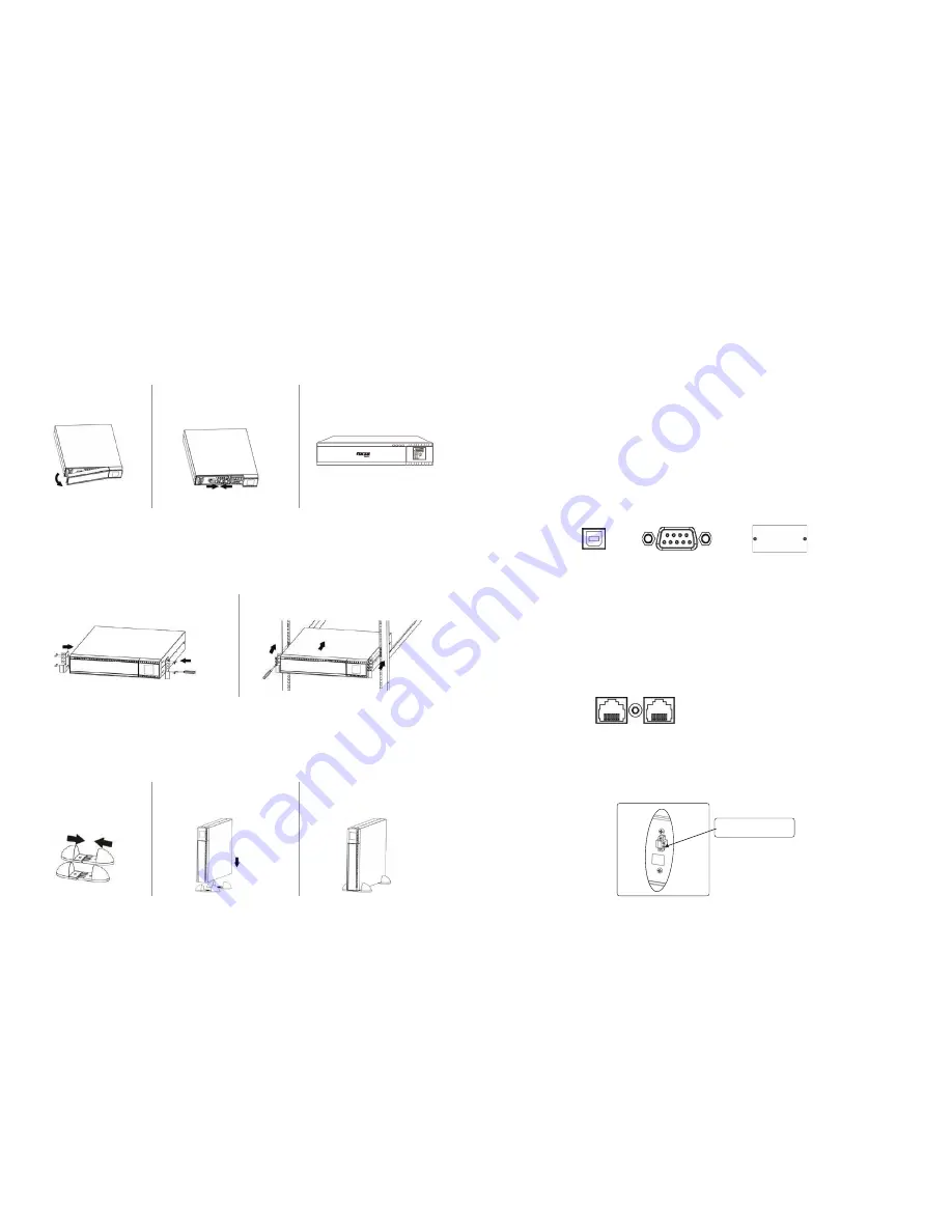
• Before installing the UPS, the user must first reconnect the wires. To do so, follow the steps illustrated below.
2-4. UPS connections
2-4.1 UPS input connection
• Plug the UPS into a two-pole, three-wire, grounded receptacle only.
• Avoid using extension cords or adapter plugs.
• Connect a single line modem/phone/fax cable into the network surge-protection “IN” jack on the rear panel of the UPS.
• Connect a network cable from the OUT jack on the rear of the UPS to a port on a PC or network device such as a router.
2-4.2 UPS output connection
2.4.3 Disabling and enabling the EPO function
For socket-type outputs, there are two kinds of outputs: programmable outlets and general outlets. Connect non-critical devices
to the programmable outlets and critical devices to the general outlets. During power failure, you may extend the backup time to
critical devices by setting shorter backup times for non-critical devices.
To allow for unattended UPS shutdown/start-up and status monitoring, connect one end of the communication cable to the
USB/RS-232 port, and the other end to the communication port of your PC. With the monitoring software installed, you can schedule
UPS shutdown/start-up and monitor its status through a PC.
The UPS is equipped with an intelligent slot perfect for either SNMP or AS400 card. When installing either SNMP or AS400 card in the
UPS, it will provide advanced communication and monitoring options.
Note:
The USB port and RS-232 port cannot be used at the same time.
CAUTION:
For 1.5K model, to reduce the risk of fire, connect only to a circuit provided with 20 amperes maximum
branch circuit overcurrent protection in accordance with the National Electric Code, ANSI/NFPA 70.
CAUTION:
For 3K model, to reduce the risk of fire, connect only to a circuit provided with 30 amperes maximum
branch circuit overcurrent protection in accordance with the National Electric Code, ANSI/NFPA 70.
Rack-mount installation
The unit comes with mounting brackets for the standard 19-inch (46.5cm) rack.
CAUTION:
Do NOT use the mounting brackets to lift the unit. The mounting brackets are only for securing the unit to the rack.
This UPS can be either placed on a desktop, mounted in a rack or installed in an upright position. Define the proper display orienta-
tion based on the configuration chosen to install this UPS.
Step 1
Remove the front panel.
Step 1
Tower installation
Allows the user to install the UPS in the upright position.
Step 2
Step 2
Connect the AC input and then
reconnect battery wires.
Step 3
Replace the front panel.
Step 1
Unfold and align the tower
support base.
Step 2
Place the UPS vertically on
the base.
Step 3
Verify that the UPS is stable and
firmly attached to the base.
•
Connect the network surge protection
Network/Fax/Phone port
The UPS has two network cable RJ45 connectors for network lines.
Keep pins 1 and 2 closed for UPS normal operation. To activate the EPO feature, remove the wire between pin 1 and 2.
Communication ports
USB port
RS-232 port
Intelligent slot
IN
OUT
Closed for UPS normal
operation
Summary of Contents for FDC-1502R
Page 1: ...2 Y e a r w a r r a n t y...


