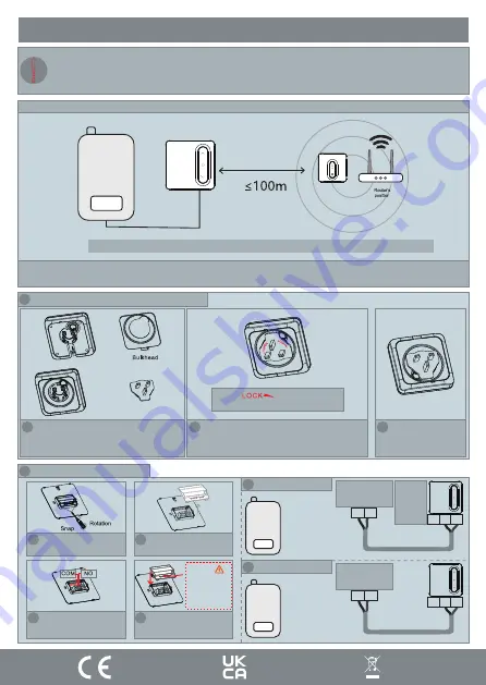
Fort ECSPST Quick Start Manual Download Page 9

Installation Plan B

Page: 8

Receiver’s 

position

Thermostat’s 

position

Boiler

Note: Distance between thermostat and receiver cannot be greater than 100m (open field).

When installing the Thermostat directly to the boiler, ensure the receiver is within the WiFi coverage area.

When the Thermostat is connected directly to the boiler, item 8 of the configuration should be “ON” .[Page 5].

As default it is set to OFF

1 Install receiver as gateway with plug adapter

1

Install rear bulkhead

2

Press and rotate to clip in the adapter

The icon “                    ” aligned with the button 

as shown, and then press down on the button

4

Complete

2 Installation Plan B Wiring

4

Reinstall safety cover

Clip

Caution: 

potential of 230V 

on connection.

Risk of electric 

shock

3

Wire into connections

1

Remove the buckle with a flat 

headed screwdriver

2

Take off safety cover

N/C COM N/O

TH TH

1 Potential Free Relay

Black & Grey 

Control 

Cables

Boiler

If NC is 

required, 

terminate 

into

COM & NC

LS LR

N/C COM N/O

2

230V Relay

Black & Grey 

Control 

Cables

Boiler

!

Our products are designed to comply with the  recommended codes of practice and to be installed and serviced by competent 

persons in  accordance with the relevant wiring regulations.

Warning: Before any installation or maintenance, ensure that the electrical supply is switched off at the breaker.

Summary of Contents for ECSPST

Page 1: ...ECSPST Quick Start Guide The latest product manuals and software is available online https www espuk com technical_support REV I22 Fort Programmable Thermostat with RF and WiFi White...

Page 2: ...Functions Page 4 Thermostat Configuration Page 5 Thermostat Installation Page 6 Installation Plan A Page 7 Installation Plan B Page 8 Pairing the Thermostat and Receiver Page 9 Product Description Pag...

Page 3: ...button Holiday mode Programming Periods 7 Day individual 5 2 split Monday Friday Saturday Sunday 6 Separate time temperature periods per day Key lock facility Low battery indication Frost protection O...

Page 4: ...Pairing Mode The LED flashes fast or slow Green ON OFF Indicator Power indicator Red Override output status Green RF indicator Yellow Output Indicator Call for heat Green Control Button With power in...

Page 5: ...rface press and hold at the same time to lock or unlock the keys When locked the thermostat will display Frost Protection If the room temperature falls below 5 C frost damage can occur To protect your...

Page 6: ...the configuration menu press and hold both the and buttons to restore the thermostat to factory settings the thermostat will display and flash 3 times This will remove any custom configuration setting...

Page 7: ...allation Note Ensure the batteries are correctly installed and the polarities are correctly aligned 2 Wall mounted 1 Desk mounted 1 Hang Thermostat on stand 2 Complete 1 Put the back board on the inst...

Page 8: ...stall the backplate onto the wall 4 Complete Brown Blue Power Supply Cables N L TH TH Black Grey Control Cables Boiler type selection The Thermostats output between N C N O Typically N O Boiler 1 Pote...

Page 9: ...ned with the button as shown and then press down on the button 4 Complete 2 Installation Plan B Wiring 4 Reinstall safety cover Clip Caution potential of 230V on connection Risk of electric shock 3 Wi...

Page 10: ...yellow constantly 2 On the Thermostat when in Standby mode press and hold for 3s 4 On the Thermostat Press the to enter pairing mode it will display and the icon will be flashing 5 If pairing is succe...

Page 11: ...ork s password before pairing the Thermostat to the ClickSmart app You can scan the above QR code to directly download the app Sign in or register following the instructions on the ClickSmart App Down...

Page 12: ...ch Worcestershire B98 8YN Tel 44 0 1527 51 51 50 Fax 44 0 1527 15 01 43 Email info espuk com Registered in England Company Registration Number 02769392 VAT Registration GB614686525 For more product in...

Reviews: