background image

12

WWW.FORNEYIND.COM

• Connect the standard MIG torch to the threaded connector on the front of the welder, tighten 

firmly by hand.


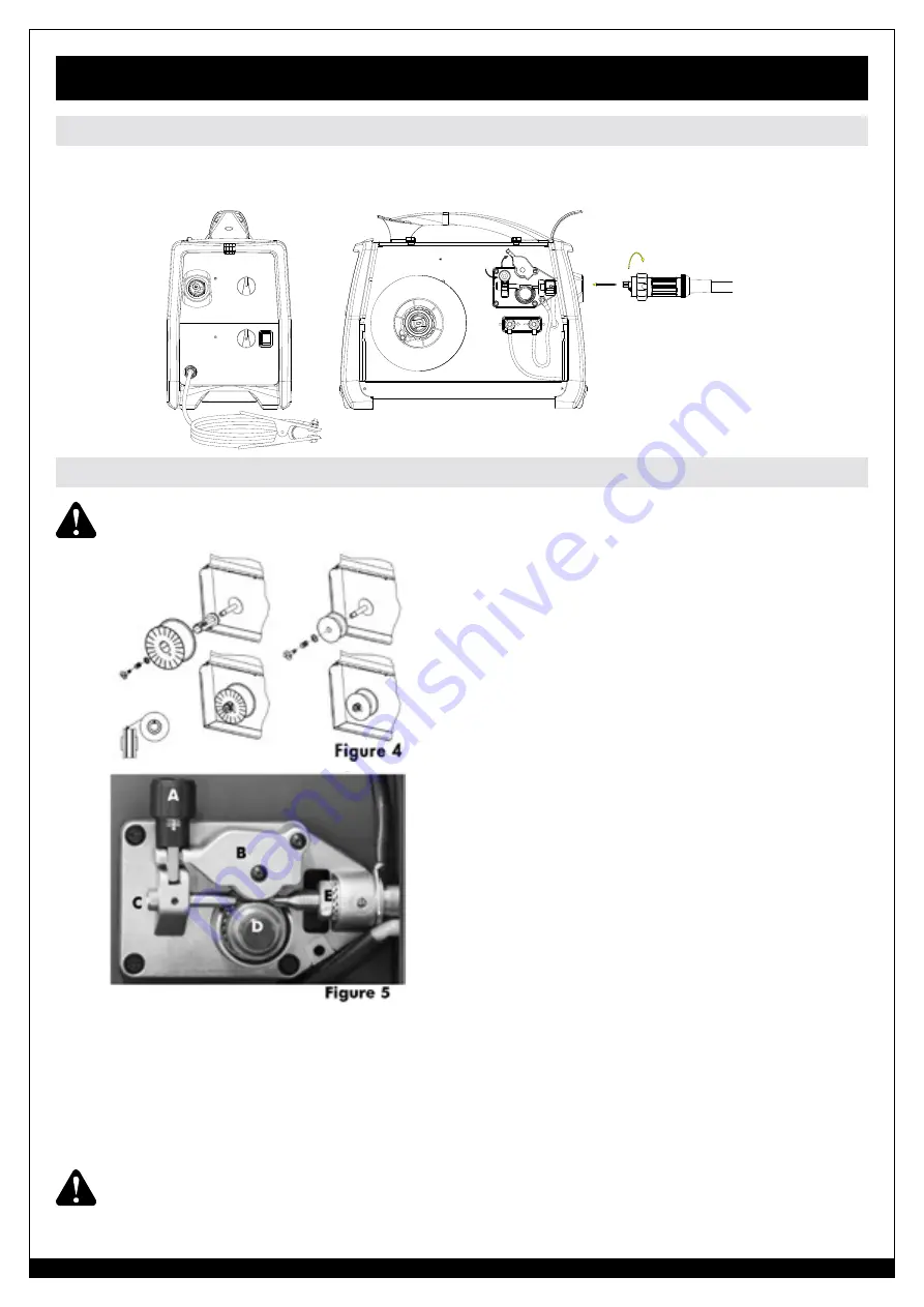
 Ensure the gas and electrical supplies are disconnected. Before proceeding, remove the nozzle 

and the contact tip from the torch.


• Open the side panel.

• Loosen the nut of the spool holder (brake drum)

and remove the spring and the external ring. (Fig.4)

• Remove the plastic protection from the spool (4) and

place the wire spool on on the spool holder.

• Mount the external ring, the spring and the

plastic lock nut again. These parts form the braking

system of the wire spool speed. NOTE: Do not

tighten the nut too much, excessive pressure strains

the wire feeding motor, while too little pressure does

not allow the immediate stop of the wire spool at the

end of the welding.

• Loosen and lower the plastic knob (A) (Fig.5). Open

the pressure arm (B) of the feeder

• Disconnect the wire from the edge of the wire spool 

being careful to keep tension on the end of the wire. 

Cut off a short section of the end of the wire to insure 

a straight end. Insert the straight end into the wire inlet 

guide (C) past the wire feed roll and into the wire liner. 

Lower pressure arm (B) and lift pressure adjustment 

knob (A) into place. Connect the input power cord and turn on the welder. Press the torch trigger 

and observe the wire feeding into the torch liner. Adjust the pressure on the wire with knob (A) 

to insure smooth feeding without slippage. Do not over tighten the  pressure adjustment as it 

may damage the motor. Close the welder side panel. Remove the nozzle and contact tip from 

the welding torch. Straighten the torch cable to remove any coils or kinks. Squeeze and hold the 

torch trigger until the wire appears at the end of the torch neck. Turn off the welder and install 

the contact tip and nozzle.

   WARNING:

 Keep the torch straight. When feeding a new wire through the liner, make sure

the wire is cut cleanly (no burrs or angles) and that at least 2 cm from the end is straight (no 

curves). Failure to follow these instructions could cause damage to the liner.

MIG, “GMAW” - Fluxcore wire, “FCAW” Welding

Torch Connection

Wire Loading

Summary of Contents for 190 MIG

Page 1: ...round Clamp 15 Power Cable Gas Hose and Regulator CAT 00318 WELDER FEATURES Welding range up to 190 Amps 230V Input Can be used for Mild Steel Stainless Steel Aluminum and Cast Iron Large cabinet with...

Page 2: ...all customer service at 1 800 521 6038 Monday through Friday from 7am 5pm Mountain Time or at www forneyind com customer_service Please take time to register your product at www forneyind com customer...

Page 3: ...g the best solutions to our customer s needs Above all our employees will provide the same respect and caring attitude within the organization as they are expected to share with every Forney customer...

Page 4: ...ustries 1830 Laporte Avenue Fort Collins CO 80521 1 800 521 6038 www forneyind com 6 Purchaser Warranty The original purchaser of the Forney Industries product The warranty is not transferable Forney...

Page 5: ...D COM WARRANTY 4 TABLE OF CONTENTS 5 SAFETY INFORMATION 6 ASSEMBLY AND MAJOR COMPONENTS 11 FRONT PANEL OPERATION 14 GENERAL OPERATING INSTRUCTIONS 15 TROUBLESHOOTING 17 SPARE PARTS AND DIAGRAMS 19 TAB...

Page 6: ...nd Educational Eye And Face Protection ANSI Standard Z87 1 from American National Standards Institute 1430 Broadway New York NY 10018 Cutting And Welding Processes NFPA Standard 51B from National Fire...

Page 7: ...ing dust and fumes Local exhaust ventilation must be provided together with adequate general ventilation and air circulation particularly when work is done in a confined space Welding process must be...

Page 8: ...e welder until the fault has been found and corrected Noise can cause permanent hearing loss Welding processes can cause noise levels that exceed safe limits You must protect your ears from loud noise...

Page 9: ...the following guidelines In areas free from moisture and dust In areas with ambient temperature between 30 to 90 F In areas free from oil steam and corrosive gases In areas not subjected to abnormal v...

Page 10: ...ore the main outlet This switch must be equipped with time delay fuses The connection with ground must be made with a two pole plug compatible with the above mentioned socket When working in a confine...

Page 11: ...e gas cylinder Turn the regulator adjustment knob counterclockwise to ensure the valve is fully closed Screw the gas regulator fully down on the gas bottle valve and fully tighten Connect the gas hose...

Page 12: ...he end of the wire Cut off a short section of the end of the wire to insure a straight end Insert the straight end into the wire inlet guide C past the wire feed roll and into the wire liner Lower pre...

Page 13: ...ders are highly pressurized Handle with care Serious accidents can result from improper handling or misuse of compresses gas cylinders Do not drop the cylinder knock it over expose it to excessive hea...

Page 14: ...5 5 5 6 7 MATERIAL Wire GAS WIRE MATERIAL THICKNESS 24 Gauge 0236 6 mm 22 Gauge 0315 8 mm 18 Gauge 0236 1 2 mm 16 Gauge 0139 1 6 mm 1 8 3 mm 1 4 6 4 mm 190 MIG SET UP CHART Arc Voltage Control Wire S...

Page 15: ...heat input suitable for heavy sections Contact the technical service of your gas supplier to know the percentages of the different gasses which are the most suitable to your application Units may be u...

Page 16: ...cannot be obtained Refer to welding set up chart on page 14 These are A Feeding wire too fast with regard to the welding voltage results in pulsing within the torch This is because the wire electrode...

Page 17: ...compressed air to periodically clean the hose liner especially when changing wire spools IMPORTANT Disconnect from power source when carrying out this operation Using low pressure air 3 5 Bar 20 30 PS...

Page 18: ...ed roller pressure Burr on end of wire Liner blocked or damaged Replace wire feeding motor Increase roller pressure Re cut wire square with no burr Clear with compressed air or replace liner Lack of p...

Page 19: ...rom the workpiece Hold the torch at the right distance Poor quality welds Insufficient gas at weld area Rusty painted oil or greasy workpiece Rusty or dirty wire Poor gound contact Incorrect gas wire...

Page 20: ...2 21 20220173 Inp Power cable3x12awg 4 5M 50a6 50p plug 1 22 04600286 Fan fan motor assy 220V 60hz 1 23 21690261 Cable holder 1 24 22210014K Thermostat 100 10a 1 pc pack 1 Tools and Spare Parts List N...

Page 21: ...21 WWW FORNEYIND COM...

Page 22: ...1 pc pack 1 05 23005360K Torch head plastic housing 1 pc pack 1 06 23005376K Black handle for m15 torch 1 pc pack 1 07 23005377K Red torch trigger 1 pc pack 1 MIG Gun Torch Spare Parts List NO PART N...

Page 23: ...23 WWW FORNEYIND COM...

Page 24: ...WWW FORNEYIND COM Forney Industries Inc 1830 LaPorte Avenue Fort Collins CO 80526 800 521 6038 www forneyind com...

Reviews:

Related manuals for 190 MIG