


-20- MBM-530NS User’s Manual
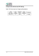
1.5 Serial Port
The ACEs (Asynchronous Communication Elements ACE1 to ACE4) are used
to convert parallel data to a serial format on the transmit side and convert
serial data to parallel on the receiver side. The serial format, in order of
transmission and reception, is a start bit, followed by five to eight data bits, a
parity bit (if programmed) and one, 1.5 (in a five-bit format only) or two stop
bits (in a 6,7, or 8-bit format). The ACEs are capable of handling divisors of 1
to 65535, and produce a 16x clock for driving the internal transmitter logic.
Provisions are also included to use this 16x clock to drive the receiver logic. Also
included in the ACE a completed MODEM control capability, and a processor
interrupt system that may be software tailored to the computing time required
handling the communications link.
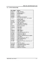
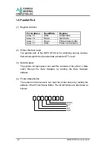
The following table is a summary of each ACE accessible register.
DLAB
Port
Address
Register
Receiver buffer (read)
0
base + 0
Transmitter holding register (write)
0
base + 1
Interrupt enable
X
base + 2
Interrupt identification (read only)
X
base + 3
Line control
X
base + 4
MODEM control
X
base + 5
Line status
X
base + 6
MODEM status
X
base + 7
Scratched register
1
base + 0
Divisor latch (least significant byte)
1
base + 1
Divisor latch (most significant byte)
(1) Receiver Buffer Register (RBR)
Bit 0-7: Received data byte (Read Only)
(2) Transmitter Holding Register (THR)
Bit 0-7: Transmitter holding data byte (Write Only)
Summary of Contents for MBM-530NS
Page 1: ...MBM 530NS User s Manual...
Page 4: ...4 MBM 530NS User s Manual...
Page 8: ......
Page 12: ......
Page 58: ......
Page 91: ...Web site www formosa21 com MBM 530NS User s Manual 91 when user tries to enter Setup utility...
Page 96: ......


