


Table of contents
3QLCLM
Edition: 04/2014
27
Terms used in the formulas:
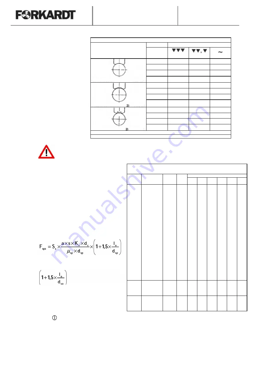
Gripping coefficient μsp
Jaw design
Material
Material surface at the gripping point
l
a
=
Overhang of the work
piece
a
=
Depth of cut
Steel
0.1
0.15
- 1 )
s
=
Feed
AI
0.1
0.14
-
K
s
=
Specific cutting force
Ms
0.09
0.14
-
GG
0.08
0.12
-
d
z
=
Machining diameter
Steel
0.12
0.20
0.32
d
sp
=
Gripping diameter
AI
0.11
0.19
0.30
μ
sp
=
Gripping coefficient
Ms
0.11
0.18
0.27
F
s
=
Primary cutting force
GG
0.10
0.16
0.26
Steel
0.25
0.35
0.50
AI
0.24
0.33
0.48
Ms
0.23
0.32
0.45
GG
0.20
0.28
0.40
1) Avoid, smooth jaws are only suitable for gripping machined surfaces
2) Indentations will be produced on the work piece.
The cutting forces increase as the cutting tool becomes dull. An additional factor of safety
S
z
=2
is recommended to allow for all uncertainties in the machining process.
The gripping force must be increased to
allow for the tilting effect caused by the
overhang
.
Specific cutting force Ks (N/mm
2
) for feed s and
Adjustment angle 70°
(Source König, Essel )
Material no.
Material
Tensile
strength
B
N / mm
2
at
m/min
Feed s (mm)
0.16
0.25
0.40
0.63
1.00
1.60
1.0401
C15G
373
100
2482
2169
1916
1687
1481
1298
The tilting force need not be taken into
account if the work piece is supported by a
tailstock or if the work piece does not
project beyond the jaws by more than 0.5 x
d
sp
. The gripping force F
spz
required can be
found approximately from the formula:
1.0501
C35G
490
100
2577
2237
1927
1668
1441
1241
1.0532
St50-2
559
100
2561
2248
1959
1716
1499
1307
1.0632
St70-2
624
100
2877
2492
2142
1851
1595
1371
1.0711
9S20
371
100
1609
1553
1497
1444
1393
1342
1.1181
Ck35V
622
100
2574
2266
1962
1741
1527
1339
1.1191
Ck45V
765
100
2524
2253
1999
1781
1584
1405
1.1221
Ck60V
673
100
2548
2296
2058
1851
1662
1490
1.3505
100Cr6G
624
100
2904
2551
2239
1968
1726
1510
1.4113
X6CrMo17G
505
100
2378
2107
1854
1638
1445
1272
1.4305
X12CrNiS18.8
638
350
2596
2192
1835
1545
1296
1065
1.5752
14NiCr14BF
658
100
2249
2012
1790
1598
1424
1266
1.5919
15CrNi6
510
100
2271
2051
1842
1661
1494
1342
1.5920
18CrNi8G
578
100
2360
2095
1847
1636
1446
1276
. Tilting factor:
17131
16MnCr5G
510
100
2641
2244
1891
1603
1354
1141
1.7147
20MnCr5G
568
100
2452
2174
1915
1694
1495
1317
1.7225
42CrMo4V
1138
100
2428
2249
2075
1919
1773
1635
1.8515
31CrMo12V
1060
100
2678
2419
2173
1960
1764
1565
1.8519
31CrMoV9V
931
100
2507
2265
2036
1836
1653
1485
3.1354
AlCuMg2
15Hv10
200
953
649
752
66»
593
525
This equation cannot be applied to stepped
work pieces whose gripping diameter is
appreciably smaller than the machining
diameter.
-
G-AlMg4SiMn
260
200
829
729
636
558
-
-
3.3561.01
G-AlMgS
75HV10
200
886
797
713
641
574
514
0.4020
GG-20
178HB
200
1637
1444
1227
1047
892
757
0.6030
GG-30
206HB
100
1919
1595
1313
108»
899
740
0.7050
GGG 50
194HB
200
1840
1606
1392
1213
1053
913
The feed thrust component F
v
and passive thrust F
p
are not entered in this
formula. They are taken into account with safety factor S
z
!
Simple jaw
FNC 50
FNC 51
Stone jaw
Roughing jaw
FNC 52


