Base-520(G) Installation
Switch Settings
SPARC/CPCI-52x(G)
Page 27
User application
The SPARC/CPCI-52x(G) provides 1 user flash EPROM devices (2M*8)
to store user applications. As factory option 2 user flash EPROM devices
(2M*8) are possible. For write-protection of the user flash EPROM see
SW4-4 in section 4.4 “Switch Settings” on page 27.
4.4
Switch Settings
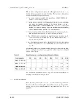
The following table lists the functions and the default settings of all
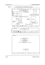
switches shown in figure 7 “Location diagram of the Base-520(G) (sche-
matic)” on page 22.
Note: Before powering up the board check the current switch
settings for consistency. Do not switch during operation.
Table 11
Default switch settings
Name and default setting
Function
SW4-1
OFF
Reset key on front-panel control
OFF = RESET key enabled
ON = RESET key disabled
SW4-2
OFF
Abort key control
OFF = ABORT key enabled
ON = ABORT key disabled
SW4-3
OFF
Boot flash EPROM write protection
(only relevant if SW6-2 = ON)
OFF = boot flash EPROM write protected
ON = boot flash EPROM write enabled
SW4-4
OFF
User flash EPROM write protection
OFF = user flash EPROM write protected
ON = user flash EPROM write enabled
ON
1
2
3
4
Summary of Contents for SPARC/CPCI-520G
Page 6: ...Contents Page iv SPARC CPCI 52x G...
Page 14: ...Using This Manual Page xii SPARC CPCI 52x G...
Page 18: ...Page 4 SPARC CPCI 52x G...
Page 20: ...Introduction Page 6 SPARC CPCI 52x G...
Page 24: ...Ordering Information Introduction Page 10 SPARC CPCI 52x G...
Page 58: ...OpenBoot Firmware Base 520 G Installation Page 44 SPARC CPCI 52x G...
Page 66: ...OpenBoot Firmware Base 520 G Installation Page 52 SPARC CPCI 52x G...
Page 102: ...Ethernet and EBus2 Devices PCIO Hardware Description Page 88 SPARC CPCI 52x G...
Page 114: ...PMC Slots with Busmode Support Hardware Description Page 100 SPARC CPCI 52x G...
Page 134: ......


