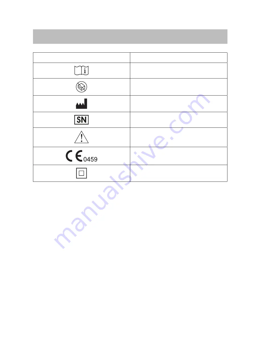
16
SYMBOL INFORMATION
Symbol
Referent
Consult instructions for use
Do not use if package is damaged
Manufacturer
Serial number
Caution, consult accompanying documentsCE Mark
Class II Equipment
Page 1: ...GW9014 TeleHealth Gateway 311 9014000 002 Version 1 0 2010 08...
Page 2: ...nts of the System 04 Appearance and Key Functions of the Gateway 05 QUICK INSTALLATION STEPS 07 GW9014A 07 GW9014B 09 LED INDICATION AND TRANSMISSION 11 NOTES ABOUT INSTALLATION LOCATION 12 PROBLEM SO...
Page 3: ...upload onto the server Users and healthcare providers can view the data remotely Data results can be viewed in various formats This device is intended to transmit selected medical information i e bloo...
Page 4: ...For GW9014B your system includes 3 3 2 2 1 1 4 4 6 7 5 5 6 FORAGW9014AGateway Owner s Manual Quick Start User Guide 1AC PowerAdapter 1 RS232 Interface Cable 1 Telephone Line 1 Ethernet Cable FORAGW901...
Page 5: ...ing green light indicates that data is transferring between the server and the gateway The green light will not be lit if disconnected WSN Data transmission status indicator of monitoring devices Stea...
Page 6: ...configuration use Please do NOT open if you are general users Power AC PowerAdapter Port Telephone Line Port Power AC PowerAdapter Port Telephone Line Port Network Cable Port RS232 Port Network Cable...
Page 7: ...4 Gateway kit and take out the contents 3 Plug power adapter into a power outlet and power adapter port on the gateway 4 Connect RS232 interface cable with any RS232 available device to RS232 port on...
Page 8: ...insert telephone line into one of the telephone line port on the gateway If you want to use telephone please insert its telephone line to another telephone line port on the gateway 5 Turn on gateway p...
Page 9: ...gs of internet router please refer to your service carrier s owner manual 2 Open FORA GW9014 Gateway kit and take out the contents 3 Plug power adapter into a power outlet and power adapter port on th...
Page 10: ...ne of the telephone line port on the gateway If you want to use telephone please insert its telephone line to another telephone line port on the gateway 4 Turn on gateway power O presents as turn off...
Page 11: ...Data transmission in process Data transmission completed After gateway turns on a green PWR indicates that the gateway is ready WSN will not be lit until the target device has connected to the gateway...
Page 12: ...er wireless devices Near a microwave or an induction cooktop In a closet or covered by other substances unable to receive signals If you upload data through a telephone line please use the telephone p...
Page 13: ...lete The table listed below is the descriptions of light signals of LED indicators As shown on page 11 Status Description LED Indicators Idle stand by Connect to Meter Transmitting End of transmission...
Page 14: ...ISP dial number is busy Operational error of remote server Connection error of internet cable or telephone line Check if PWR is lit Check if the gateway power is on Check if the power supply is secur...
Page 15: ...Environment 20 C 65 C below 90 R H Non condensing Model no GW9014B Input Interface Bluetooth Output Interface ISP dial up service or Ethernet Dimension 170mm x 120mm x 30mm Weight 221 8g Power AC powe...
Page 16: ...16 SYMBOL INFORMATION Symbol Referent Consult instructions for use Do not use if package is damaged Manufacturer Serial number Caution consult accompanying documents CE Mark Class II Equipment...