


12
5-3. HD to SD (with Genlock)
This operation example shows how to convert HD-SDI video to SD-SDI video with using a
genlock signal. The 16:9 HD video is converted to 4:3 SD video by
horizontally filling
a 4:3
screen (letter box type). . The output video is synchronized with the genlock signal. Adjust the
genlock phase in the menu.
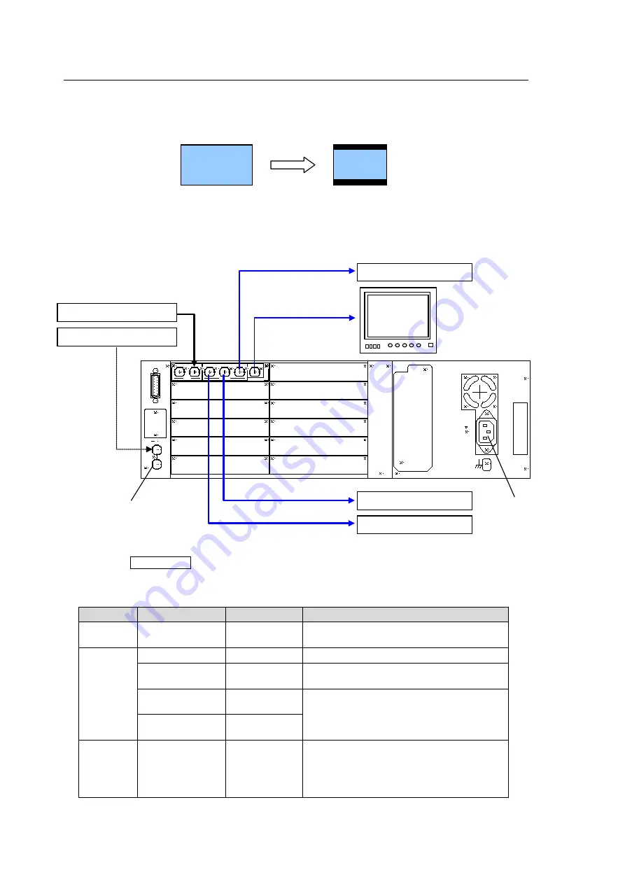
Connection
1) Connect the OSD OUT port to NTSC (PAL) monitor.
2) Input an HD-SDI signal to the [INPUT-3G/HD/SD] port.
3) Connect the [OUTPUT-3G/HD/SD 1] port or [OUTPUT-3G/HD/SD 2] port to a waveform
monitor or an SDI monitor.
4) Input a genlock signal (BB) to the UFM frame.
5) Power on the UFM frame.
Conversion Setting
1) Press the MENU OSD button to display the menu on the NTSC (PAL) monitor.
2) Make settings as shown in the table below. See section 4-2. "Menu Operation" for details on
menu operation.
Menu
Item
Setting
Description
Input
Source
SDI
Selects
SDI
for input port. The video
format is automatically set.
Output
Output
SD
Selects
SD
for output video format.
Genlock
Reference
lock
Sets reference mode to
Reference lock
.
Genlock H
Phase
(±1/2H)
Adjusts horizontal phase and vertical
phase monitoring the waveform monitor.
Genlock V
Phase
(±1/2V)
Scaling
SD out format
16:9 LB
When set to
16:9 LB
, the aspect ratio of
the video is preserved, the left and right
edges are fitted and black bars are added
to the top and bottom. See section 6-2
Down-conversion (HD to SD),
R
A
T
IN
G
L
A
B
E
L
G
E
N
L
O
C
K
I
N
A
L
A
R
M
A
C
1
0
0-
2
4
0V
~
5
0
/6
0H
z
IN
F
A
N
A
L
M
UFM-30UDC
OUTPUT
INPUT
COMPOSITE
3G/HD/SD-SDI
3G/HD/SD-SDI 1
3G/HD/SD-SDI 2 SDI MONITOR
OSD OUT
Power Source
75 ohm termination required
if not looped through.
Out 2 (SD-SDI)
Out 1 (SD-SDI)
Menu display
and
Output video
Preview Out (SD-SDI)
Input (HD-SDI)
Genlock Signal
UF-112 rear panel
16:9


