


7
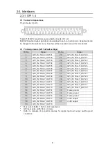
2-2. Rear Panel
No.
Name
Description
A
LAN
For switcher (MU) connection via LAN
Ethernet (10/100BASE-TX
)
B
SERVICE
For service use (Setup menu settings by serial connection)
C
DC12V IN 1
DC12V IN 2
For 12 VDC power input
D
SERIAL 1
SERIAL 2
SERIAL 3
SERIAL 4
For RS-232C / RS-422 control connection. (*1)
RS-232C or RS-422 can be selected using switches on the
card. (Default: RS-232C)
► See Sec. 2-4. “Internal Settings.”
E
GPI 1
(
Port 1
)
For GPI input/output
(Function (input and output) free assignable, 32 for each)
F
GPI 2
(
Port 2
)
G
GPI 3
(
Port 3
)
H
GPI 4
(
Port 4
)
(*1) Serial interface extension may not be disabled depending on connection circumstances.
Refer to connection device manuals to select RS-232C or RS-422.
A
B
C
D
E
F
G
H
LAN
GPI 1
GPI 2
GPI 3
GPI 4
2 - DC12V IN -1
RATING LABEL
SERIAL
SER VICE
1
2
3
4