


12
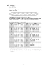
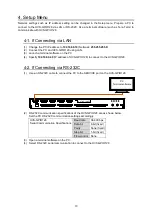
3. Connecting to the HVS Switcher
(1) If network settings in the system are factory default settings, go to Step (2).
If network settings such as the HVS switcher LAN1 port address are changed from default, refer to
the next chapter and change network settings in the Setup menu to the current ones.
(2) Connect HVS-GPIO128 to the HVS Series switcher (MU) via LAN.
Use a LAN switch to connect HVS-GPIO128 to LAN 1(MAIN) on the switcher.
(3) Connect HVS-GPIO128 to serial control devices.
Use the HVS switcher menu to set up the devices.
(4) Connect HVS-GPIO128 to GPI controllers.
Use the HVS switcher menu to set up the devices.
(5) Use the supplied AC adapters to supply power to HVS-GPIO128.
LAN
GPI 1
GPI 2
GPI 3
GPI 4
2 - DC12V IN -1
RATING LABEL
SERIAL
SER VICE
1
2
3
4
LAN switch
HVS Series MU
LAN 2
(SUB)
HVS-GPIO128
LAN 1
(MAIN)
PC for
HVS-GPIO128
Setup
AC adapter
AC adapter
HVS-2000 (default)
192.168.0.80 / 24
Default:
192.168.0.40 / 24
PC IP address
192.168.0.10 / 24
Serial Controller
(Editor, Video server, etc.)
GPI Controller
RS
-23
2C
RS-232C/RS-422
10
0
B
A
S
E
-TX