EN
- 6 -
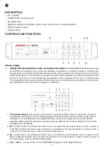
4.-
VOL -/VOL +
: volume control for the bluetooth receiver.
5.-
PAIR
: hold this button down for a few seconds to link your mobile telephone to the bluetooth receiver
module. The LED indicators on the module will flash alternately. With the bluetooth option activated on
your mobile telephone, select the BT 2.1 device from the list of bluetooth devices. If you are asked for
a password, insert “0000”. It will make a noise to confirm it and the LED indicator on the right will stay
alight. Now your mobile telephone is linked to your equipment.
3.-
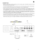
INPUT 1-4
: volume controls for INPUTs 1 to 4.
4.-
AUX
: volume control for the auxiliary input.
5.-
BASS
: to strengthen or weaken the bass frequencies ±10 dB.
6.-
TREBLE
: to strengthen or weaken the treble frequencies ±10 dB.
7.-
MASTER
: control for regulating the MASTER output volume for all inputs.
8.-
SIG
: LED indicator for the output signal level. It lights up in green when it receives a signal in any of its
inputs.
9.-
PEAK
: LED indicator for the saturation level. It lights up in red when there is an excess signal in some
of the inputs. It regulates the MASTER volume or what comes from the rest of the inputs that this
indicator does not light up for.
10.-
POWER
: amplifier on/off switch.
BACK PANEL
1.-
Ventilation grille
: for ventilating the final power step.
2.-
GND
: screw for earth, for use if the mains does not already have it incorporated.
3.-
115 V/230 V
: power voltage selector.
4.-
AC socket
: for connecting the AC power cable.
5.-
FM
: aerial input for the digital FM tuner.
6.-
AMP IN/PRE OUT
: the connection bridge between the 2 RCA connectors communicates the output
signal from the PRE OUT output to the AMP IN input.
7.-
LINE OUT
: auxiliary line output. Output signal for recording, mixer, power amp, etc., 2 x RCA
connectors.
8.-
AUX
: auxiliary input. Signal source input, for connecting through audio source RCA connectors.
9.-
LINE/PHANTOM 24 V/MIC
: input and 24 V phantom sensitivity switches. These switches have three
positions.
LINE
: in this position, line level audio sources can be connected to inputs 1 to 4: audio players, etc.
MIC
: in this position, low impedance 30-600 Ω dynamic microphones can be connected to inputs 1 to
4.
PHANTOM 24 V
: in this position, electret condenser microphones that need 24 V power can be
connected to inputs 1 to 4.
10.-
INPUT 1-4
: microphone/line inputs that use a combo connector (XLR and 6.3 mm stereo jack),
accepting balanced and unbalanced 30-600 Ω microphone signals and balanced electret condenser
Summary of Contents for MA-125RGUB
Page 10: ...BLOCK DIAGRAM 10 EN...

