background image

4.-

Operating mode selector.

5. 

Power supply input 230/115 V AC.

6.-

BREAKER

: resettable fuse, 10 A. When the power amp is overloaded or there is a surge, the fuse will

be cut off to avoid damage. It is reset by pressing it. 

7.-

Power supply voltage selector.

8.-

GND

: earth connection terminal.

9.-

OUTPUTS

: loudspeaker output terminals. Use just one output depending on the charge impedance: 4

or 8 Ω low impedance lines or 70 or 100 V high impedance lines. Connect the loudspeakers between
the  COM terminal and one of the output terminals: 4 Ω, 8 Ω, 70 V or 100 V.

CONNECTION

-

Before making any connections make sure that all the equipment has been switched off.

-

Check the the CH 1 and CH 2 volume controls are at their minimum.

Depending on the desired application, 3 operating modes can be selected using the switch on the back of
the equipment: parallel mode (PARALLEL), stereo mode (STEREO) and bridge mode (BRIDGED).

PARALLEL MODE (PARALLEL)

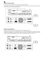
Move the switch on the back of the power amp to the PARALLEL position. 

In this mode, the input for the 2 channels will be the CH 1 channel input signal. Connect the CH 1 channel
input and the 2 loudspeaker outputs. The output volume in the 2 channel is adjusted separately.

- 5 -

EN

Summary of Contents for FS-2503E

Page 1: ...FS 2503E 2 CHANNEL POWER AMPLIFIER WITH 100 V LINE OUTPUT INSTRUCTION MANUAL...

Page 2: ...llow ventilation Avoid direct sunlight heat sources and excessive dust Do not place the machine near magnetic elds or static electricity Do not use surfaces which vibrate or receive impact Do not pile...

Page 3: ...ler when purchasing a similar product at no additional cost It also shows that the machine was put on the market after 13th August 2005 European Community Directive 2012 19 EU of Electrical and Electr...

Page 4: ...ion activated the audio output is cut off 4 CLIP LED peak signal indicators They light up when an input signal is detected with a level that is too high in the corresponding channel or when there is a...

Page 5: ...one of the output terminals 4 8 70 V or 100 V CONNECTION Before making any connections make sure that all the equipment has been switched off Check the the CH 1 and CH 2 volume controls are at their m...

Page 6: ...s adjusted separately BRIDGE MODE BRIDGED Move the switch on the back of the power ampli er to the BRIDGED position In this mode lthe input for the 2 channels will be the CH 1 channel input signal The...

Page 7: ...peaks and eliminate uctuations caused by turning the the ampli er on Furthermore it is equipped with a 10 A BREAKER resettable fuse on the back panel If the fuse is cut off due to a surge or excessive...

Page 8: ...ge produced by inappropriate use or negligence accidents worn out parts due to use breakages burns spilt liquids or other substances excessive humidity battery deterioration and internal manipulation...

Reviews: