- 22 -
ID DIP-SW
6
6
.
.
2
2
T
T
r
r
a
a
n
n
s
s
m
m
i
i
t
t
t
t
e
e
r
r
C
C
h
h
a
a
n
n
n
n
e
e
l
l
S
S
e
e
t
t
t
t
i
i
n
n
g
g
s
s
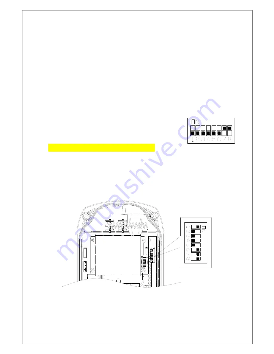
Transmitter channel settings (Select the channel you would like to operate. Do not exceed
the channel limit)
6.2.1 Set by programming tool
6.2.2 Set by encoder board 2
nd
& 3
rd
pin of JP1 and dip-switch
To set the frequency on JP1 of TX board, put jumper on 2
nd
& 3
rd
pin of JP1. Set the frequency needed
by changing the dip-switch setting. Repeat the previous steps to set another frequency.
Example
:
Set channel as 03
→
(00000011)
→
Correct setting
7
7
.
.
R
R
E
E
C
C
E
E
I
I
V
V
E
E
R
R
S
S
E
E
T
T
T
T
I
I
N
N
G
G
S
S
7
7
.
.
1
1
H
H
o
o
w
w
t
t
o
o
s
s
e
e
t
t
α
α
6
6
0
0
4
4
/
/
6
6
0
0
7
7
/
/
6
6
0
0
8
8
/
/
6
6
1
1
2
2
R
R
e
e
c
c
e
e
i
i
v
v
e
e
r
r
I
I
D
D
C
C
o
o
d
d
e
e
s
s
7
7
.
.
1
1
.
.
1
1
H
H
o
o
w
w
t
t
o
o
s
s
e
e
t
t
α
α
6
6
0
0
4
4
/
/
6
6
0
0
7
7
/
/
6
6
0
0
8
8
R
R
e
e
c
c
e
e
i
i
v
v
e
e
r
r
I
I
D
D
C
C
o
o
d
d
e
e
s
s
Top slot
“1”
Bottom slot
“0”
Set the ID codes needed with the dip-switch on the decoder board. For example: the ID codes set above
10000111.


