- 34 -
2 5 5 mm
2 7 8 mm
4 - O10.5
If it is unavoidable, please consider using antenna with external coaxial cable to relocate the
antenna to better signal receipt position.
3.
Always locate the receiver unit as far away from high voltage wiring or equipment, such as: motor,
relay, magnetic valve, inverter controls and output cable…etc. as possible. Be sure to install the
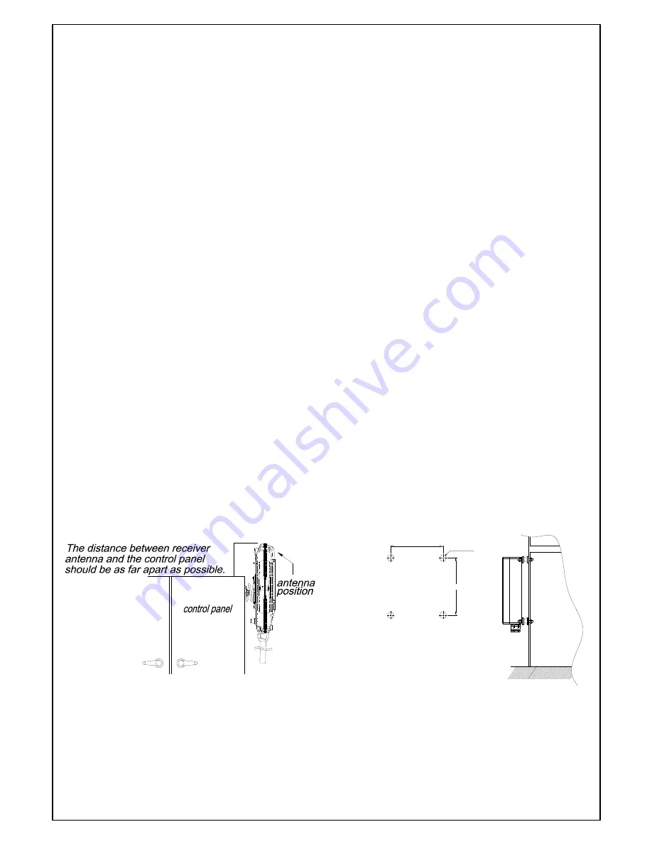
receiver at least 2 meters away from the inverter. If the receiver is installed on the control box,
then the antenna position has to be higher than the control box. (as Fig.14)
α612
Drill four holes (dia.10.5mm) base on the position of the receiver shock absorbers. (Fig.15)
9.2.2 Commissioning steps
1. Decide the wiring type and cable. If the cable gland is used for the cable, please use the enclosed
rubber cork to seal the cable gland without cable.
2. For system wiring, please refer to the output contact diagrams from page 13.
3. Ensure the selected location has adequate space to accommodate the receiver enclosure.
4. Make sure the receiver unit is in upright position (vertical).
NOTE!! The distance between the antenna and the control panel should be as far apart as
possible
(refer to the fig.14 & 15).
5. If a crane or equipment’s runway is longer than 100 meters, an external antenna should be added.
The Alpha 608 receiver housing has provisions for an external factory installed antenna available as
an option, contact your dealer for price and delivery.
6. Drill a hole on the control panel (10.5mm).
7. Tightened the bolt nuts provided.
8. If the control panel has a plastic surface, extended grounding wire should be used.
9. Ensure all wiring is correct and safely secured and all screws are fastened.
(Fig.14) Alpha 604, 607,
608 Models
(Fig.15) Alpha 612 Models


