background image

12

Service

Ice machine operation (all models)

Follett’s ice machine consists of fi ve distinct functional systems covered in detail as follows:

• Water system
•  Electrical control system
• Mechanical assembly
• Refrigeration system
• Bin full

The Horizon ice machine overview

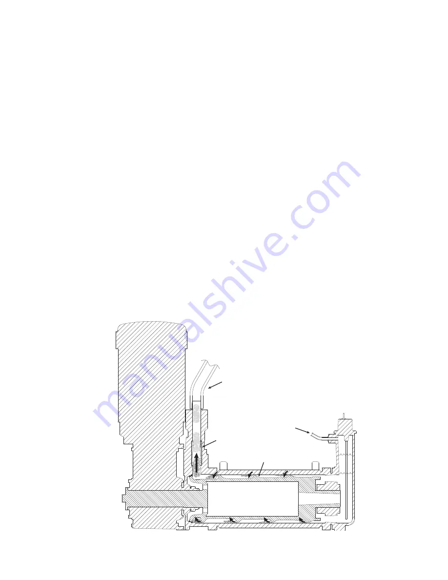
The Follett Horizon ice machine uses a horizontal, cylindrical evaporator to freeze water on its inner surface. The 
refrigeration cycle is continuous; there is no batch cycle. The evaporator is fl ooded with water and the level is 
controlled by sensors in a reservoir. A rotating auger (17 RPM @ 50Hz) continuously scrapes ice from the inner 
wall of the evaporator. The auger moves harvested ice through the evaporator into an ice extrusion canal. The ice is 
forced through a restrictive nozzle that squeezes out the water and creates the Chewblet. The continuous extrusion 
process pushes the Chewblets through a transport tube into a dispenser or bin. 

A solid state PC board controls and monitors the functionality of the ice machine. In addition to sequencing electrical 
components, the board monitors various operational parameters. A full complement of indicator lights allows visual 
status of the machine's operation. Additionally, the PC board controls the self-fl ushing feature of the ice machine. The 
evaporator water is periodically drained and replenished to remove minerals and sediment.

A unique “bin full” detection system is incorporated in the Horizon ice machine. A sensor located at the ice discharge 
port of the machine detects the position of the transport tube. When the bin fi lls up with ice, the transport tube 
moves out of the normal running position, and the sensor turns the ice maker off. A domed housing at the end of the 
transport tube contains the ice extrusion loads during shut down.

water
inlet

auger

compression
nozzle

ice 
transport 
tube

Harvest system diagram

Summary of Contents for C20000

Page 1: ...n PA 18040 USA Toll free 877 612 5086 1 610 252 7301 www follettice com Following installation please forward this manual to the appropriate operations person Operation and Service Manual After Serial...

Page 2: ...2...

Page 3: ...or refrigerant solenoid output Wiring diagram Compressor data Gearmotor data Resistance of windings Mechanical system Evaporator disassembly Evaporator reassembly Refrigeration system Refrigeration pr...

Page 4: ...454 lbs 206kg 700 up to 750 lbs 340kg 1000 up to 1036 lbs 471kg 1400 up to 1450 lbs 658kg 1650 up to 1580 lbs 717kg V Vision H Harmony B Ice storage bin J Drop in M Ice Manager diverter valve system...

Page 5: ...llation of Follett model 00130286 activated carbon filter in ice machine inlet water line Ambient Air temperature 100 F 38 C max 50 F 10 C min Water temperature 90 F 32 C max 45 F 7 C min Water pressu...

Page 6: ...ton Pennsylvania 208264 AMPS AMPS VOLTS SERIAL NO CORPORATION MODEL Service No Product Module No REFRIGERANT FULL LOAD AMPS Stock Module Identification Plate DESIGN PRESSURE HIGH SIDE MAX BRANCH CIRCU...

Page 7: ...ss cleaner such as 3M Stainless Steel Cleaner Polish or equivalent Monthly condenser cleaning air cooled ice machine only 1 Use a vacuum cleaner or stiff brush to carefully clean condenser coils of ai...

Page 8: ...WATER light comes on Fig 2 Note Do not use bleach to sanitize or clean the ice machine HI WATER Fig 2 12 Fig 3 LO WATER N A E L C Fig 4 3 Replace cover on cleaning cup Wait until machine restarts Mach...

Page 9: ...SANITIZER Fill until HI WATER light comes on Fig 5 Note Do not use bleach to sanitize or clean the ice machine 6 Replace cover on cleaning cup Wait until machine restarts Machine will sanitize then fl...

Page 10: ...ng disposable food service grade gloves insert dry Sani Sponge kit part 00132068 Next insert Sani Sponge soaked in Nu Calgon IMS II sanitizer solution Push both Sani Sponges down ice transport tube wi...

Page 11: ...wer switch ON Ice pushes Sani Sponges through tube Fig 11 12 Place a sanitary 2 gallon or larger container in bin or dispenser to collect Sani Sponges and ice for 10 minutes Collect 5 5 lbs 3kg of ice...

Page 12: ...extrusion process pushes the Chewblets through a transport tube into a dispenser or bin A solid state PC board controls and monitors the functionality of the ice machine In addition to sequencing elec...

Page 13: ...will sense the activation During normal operation the water level rises and falls between the Normal High and Normal Low sensors As water is consumed to make ice the level will fall until the Normal...

Page 14: ...ion and auger drive systems immediately shut down Note The fan motor will continue to run for 10 minutes to cool condenser The TIME DELAY light comes on initiating the time delay period When the time...

Page 15: ...he drain clog sensor located in the plastic drain pan behind the drain solenoid will detect the presence of water just below the top edge of the pan If water does not properly flow out of the drain pa...

Page 16: ...C NO L1 J7 J4 J5 MOTOR FAN J17 J18 J2 BRN BLU 1 2 3 J50 6 Amp Max 1 2hp Max NO C K3 J6 M2 M1 2 12 9 1 3 GRN 34 CB1 COMP SOL FAN DRV 19 18 SNUBBER 20FLA 240Vac CONTACTOR K10 L2 L1 2 5 7 8 S1 O I 240Vac...

Page 17: ...7 8 7 8 8 1 Water cooled Condenser water temp 50 F 10 C 60 F 16 C 70 F 21C 80 F 27 C 90 F 32 C 7 0 7 0 7 4 6 7 8 0 Locked rotor amps 54 Gearmotor data Brother Gearmotor current 2 8A nominal Locked rot...

Page 18: ...nscrew and remove stream divider as shown 3 Unplug and remove gearmotor as shown 4 Remove all traces of petrol gel from the auger shaft Fig 13 Fig 14 Fig 15 5 Unscrew and disconnect transport tube fro...

Page 19: ...9 Fig 16 8 Loosen nut on V band clamp and remove 9 Remove V band clamp from front of evaporator 10 Remove main housing as shown Fig 17 11 Remove and discard mating ring and seal 12 Carefully remove au...

Page 20: ...liquid soap in the area shown and slip on seal and spring Note Do not touch the sealing surfaces Use cardboard disk to install Fig 20 5 Reinstall main housing as shown Fig 18 Evaporator reassembly 1 R...

Page 21: ...g sure that insulation is properly seated between gearmotor and main housing as shown 16 Firmly tighten four gearmotor bolts in place removed for clarity Note Shuttle housing Fig 21 6 Orient auger sha...

Page 22: ...26 21 Lubricate body of stream divider with petrol gel and reinstall 22 Plug gearmotor power cord into electrical box Fig 24 17 Insert a bolt into the auger shaft and finger tighten 18 Using a wrench...

Page 23: ...ge suction 218 31 241 33 277 35 313 38 349 41 1503 213kPa 1661 234kPa 1909 241Kpa 2158 262kPa 2406 282kPa 15 03 2 13bar 16 61 2 34bar 19 58 2 41bar 21 58 2 62bar 24 06 2 82bar Water temperature Water...

Page 24: ...the factory warranty Evacuation Evacuate the system to a level of 500 microns When the 500 micron level is reached close all valves Allow the system to sit for approximately 20 minutes During this pe...

Page 25: ...f the flag is down out of the sensor When the bin fills to the top and ice can no longer move through the tube the machine will force the shuttle flag up into the sensor shutting the machine off The s...

Page 26: ...properly installed thermostat open 4 Transport tube backed out of coupling 1 Correct transport tube routing 2 Repair or replace shuttle mechanism 3 Replace or reposition thermostat 4 Correct coupling...

Page 27: ...lenoid may cause an errant drain clog 1 Remove kink or blockage from drain hose 2 Re route floor drain 3 Clean area around drain sensor and or replace Drain solenoid valve 8 Ice machine is making ice...

Page 28: ...cement parts Evaporator assembly Order parts online www follettice com 8 9 12 11 10 36 28 38 39 23 33 37 40 32 29 34 17 18 18 30 26 23 24 25 24 24 27 23 35 31 23 13 14 15 16 1 3 19 17 23 28 18 5 20 21...

Page 29: ...0880 23 Elbow water 1 4 x 3 8 OD 00988030 24 Tubing water 1 4 OD 502079 25 Hardware mounting evaporator cap 00130989 26 Solenoid water feed 240V 00130831 27 Tee water 00134494 28 Sensor assembly water...

Page 30: ...30 12 11 5 13 14 15 6 4 1 2 3 8 7 10 9 Air cooled assembly 30 Order parts online www follettice com...

Page 31: ...b TXV 00106534 7 Drier 502724 8 Valve expansion thermal includes 502830 and 00106534 00130997 9 Insulation TXV 502830 10 Hardware evaporator mounting base set of four 00130971 11 Compressor includes s...

Page 32: ...32 32 Water cooled assembly 5 11 12 13 13 10 6 19 20 17 18 1 4 2 8 7 9 15 16 15 12 14 3 11 13 13 21 Order parts online www follettice com...

Page 33: ...34 00130997 9 Insulation TXV 502830 10 Condenser w c 00117234 11 Elbow water 90 00129478 12 Valve shut off water 502222 13 Coupling 206411 14 Hardware evaporator mounting base 00130971 15 Ty rap 20458...

Page 34: ...34 34 Electrical box 1 2 6 4 5 7 8 9 10 3 15 14 13 12 11 Order parts online www follettice com...

Page 35: ...lamp run capacitor 00117044 6 Relay compressor starting includes wire harness 00141648 7 Contactor 00917195 8 Capacitor compressor starting 00141663 9 Cap capacitor 00123216 10 Bracket capacitor 20762...

Page 36: ...Integration kit top mount and RIDE remote ice delivery equipment Order parts online www follettice com 8 7 6 5 4 11 12 11 12 8 7 6 5 4 13 2 1 10 2 2 10 9 2 1 Top mount configuration RIDE model configu...

Page 37: ...ulation actuator 00168930 13 Ice transport tube top mount 30 762 mm 00171306 Not shown Integration kit top mount 00171389 Not shown Integration kit RIDE model includes 10 3m of tube and insulation 001...

Page 38: ...NCH CIRC UIT FUS E SIZE MIN BRA NCH CIRC UIT AMP ACIT Y DE SIG N PR ES SU RE HIG H SID E AM PS AM PS C R RE FR IGE RA NT Eas ton Pen nsy lvan ia VO LTS CH AR GE LO W SID E HZ PAR T NO CO RP OR ATI ON...

Page 39: ...ng includes 00144675 00171207 9 O ring 00144675 10 Bulkhead fitting 00171215 11 Nut 00902338 12 Hose clamp 500377 13 Plate strain relief 00192070 14 Louvered docking assembly includes reference s 3 4...

Page 40: ...18040 USA Toll free 877 612 5086 1 610 252 7301 www follettice com Horizon Harmony Ice Manager SafeCLEAN Sani Sponge and Vision are trademarks of Follett Corporation Chewblet RIDE and Follett are reg...

Reviews: