SETUP AND OPERATION
| ENGLISH
19
MOUNTING WITH WLX-100 / WLX-221 WALL BRACKETS
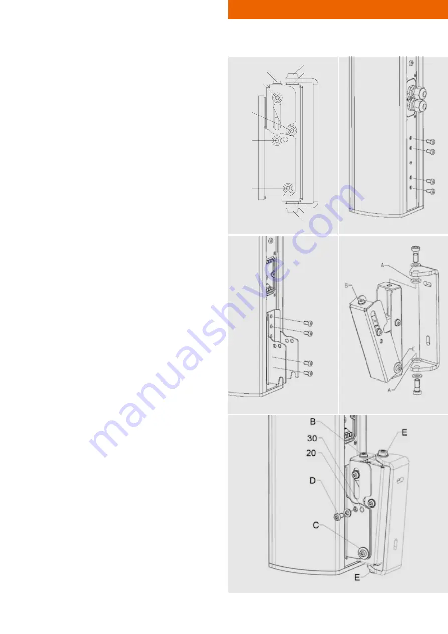
1. Remove both oval-head screws M6 (D) at the mount-
ing plate and loosen the screws (C, F, G) by about three
turns. Remove the mounting plate from the wall bracket.
SEE FIGURE 4.
2. Remove the four to six M6 oval-head screws that are lo-
cated underneath the connector panel.
SEE FIGURE 5.
3. Fix the loudspeaker to the
WLX-100/WLX-221
mount-
ing plate. Apply medium-strength thread lock fluid to
all screws. On both brackets, use four of the locking
screws you just removed. Tighten all screws according
to the required torque.
SEE FIGURE 6.
4. Fix the
WLX-100
or
WLX-221
to the building structure
using two screws and wall plugs. To do this, you will
need to disassemble the mounting bracket from the wall
bracket. During installation, don‘t forget to place the two
tooth-lock washers (A) between the mounting bracket
and the wall bracket. Make sure that the wall brack-
et is mounted with the horizontal slot facing upward.
SEE FIGURE 7.
5. Put the mounting bracket in a roughly vertical position by
turning the adjustment spindle (B) to the right.
6. Place the loudspeaker and its mounting plate on the
wall bracket. Both sides of the mounting plate must be
resting on the screw (C).
SEE FIGURE 8.
7. At this point the fixing screws (D) can be fitted and
tightened with a torque of 8-10 Nm. There are two op-
tions here: If the front holes (20) are to be used, this will
result in an adjustment angle of 0-20°; if the rear holes
(30) are used, this will result in an adjustment angle of
10-30°.
8. Set up the required inclination angle by turning the ad-
justment spindle (B) to the left. If you need to reduce
the angle again, turn the spindle back while pushing
the speaker slightly up towards the wall bracket and
thus releasing the spindle.
9. Loosen the clamping screws (E) on the horizontal axis
and turn the loudspeaker to its required position.
10. Once you are happy with the loudspeaker’s angle and
rotation, tighten the clamping screws (E) with a torque
of 20 Nm. Tighten the screws (C, F, G) with a torque of
8 to 10 Nm.
Figure 4
Figure 6
Figure 8
Figure 5
A
E
E
A
C
D
F
G
B
Figure 7


