background image


SENSOR SYSTEM Ro 35 L 

4.3 Adjusting nominal diameter 

OPERATION 

4-12


6.461.21 - 2008/06 

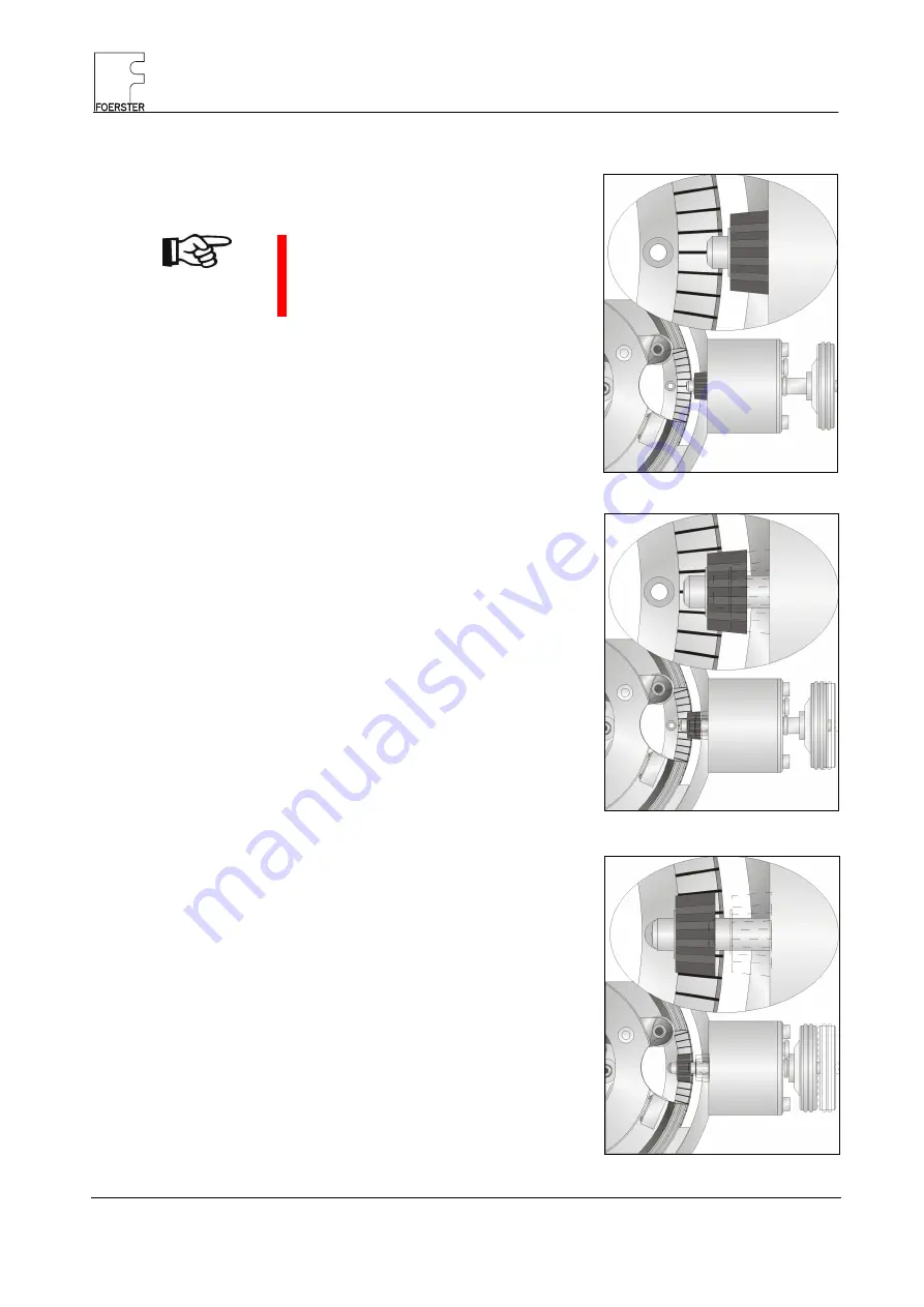
Changing adjustment value 

NOTE

Brake the rotating head to 
a standstill with the hand 
brake before adjustment! 


Push in the hand wheel 
and turn until the actually 
valid diameter has reached 
the adjustment position. 


Push in the hand wheel 
completely in adjustment 
position and set new nominal 
diameter. 


Pull the hand wheel back 
into idle position. 

Fig. 4.13  Idle position 

Fig. 4.14  Finding adjustment position 

Fig. 4.15  Adjustment position 

Summary of Contents for 6.461.21

Page 1: ...CIRCOGRAPH Sensor system Ro 35 L 6 461 21 Operating Instructions...

Page 2: ......

Page 3: ...Instructions is essential for avoiding equip ment faults and for ensuring trouble free operation It is therefore of the utmost importance that the entire Operating Instruc tions are made known to and...

Page 4: ...mation All rights reserved INSTITUT DR FOERSTER GmbH Co KG These operating instructions are intended for assembly operating and monitoring personnel Copying reproduction or translation of these oper a...

Page 5: ...ed operators 1 3 1 9 Personal safety equipment 1 4 1 10 Safety measures at the installation location 1 4 1 11 Protective safety devices 1 4 1 12 Behaviour in the event of an emergency 1 4 1 13 Declara...

Page 6: ...ter 4 5 4 3 1 Preparation 4 5 4 3 2 Removing nozzle holder 4 6 4 3 3 Changing nozzles 4 8 4 3 4 Adjusting probe clearance 4 9 4 3 5 Adjusting roller guide 4 13 4 4 Rotational speed preselection 4 13 4...

Page 7: ...icing and maintenance of the machine must be appropriately qualified and must strictly follow the information provided in these operating instruc tions Your safety is at stake 1 2 Safety information a...

Page 8: ...nly in conjunction with a suitable conveying mechanism and a lifting table On no account may you convert or modify the sensor system arbitrarily for reasons relating to safety DANGER Masses rotating a...

Page 9: ...protective safety devices or render them inoperable by making modifications to the system 1 7 Workstations The workstation is located on the electronic equipment cabinet or on the operating panel of...

Page 10: ...on is always clean and unobstructed by issuing appropriate in company instructions and con ducting inspections 1 11 Protective safety devices The CIRCOGRAPH sensor system is shut down when opening the...

Page 11: ...121 140 488 72766 REUTLINGEN info foerstergroup de GERMANY www foerstergroup de Product CIRCOGRAPH Sensor system Ro 35 L Type 6 461 21 We declare that this product complies with the requirements of fo...

Page 12: ...SENSOR SYSTEM Ro 35 L 1 13 Declaration of Conformity SAFETY 1 6 6 461 21 2008 06 Notes...

Page 13: ...esting also separate piece testing Surface free of scale wherever possible bright Testing without physical contact at rotational speeds up to 9 000 rpm End condition free of projecting burrs Max test...

Page 14: ...e a flaw of a certain length The test speed is a result of the number of rotating probes integrated in the rotating head 2 or 4 test levers the track width of all probes and the rotational speed rpm T...

Page 15: ...the connection cables are re quired for a complete test system besides the sensor system which scans the test material and generates the eddy current signal Separate leaflet CIRCOGRAPH DS System 6 430...

Page 16: ...21 2008 06 Nozzle Holder Outside Nozzle Outside Nozzle Inside Nozzle Holder Inside Fig 2 2 CIRCOGRAPH sensor system Ro 35 L Roller guide left 4 5 35 6 461 01 5001 Roller guide right 4 5 35 6 461 01 5...

Page 17: ...chamber surrounding the test zone serves the purpose of contact and burst protection as well as dust collection This chamber is provided with a connection facility for a suction connector for an exte...

Page 18: ...environmental conditions at the testing location the probes are protected by a ceramic armor nevertheless replacement of probes is possible As already mentioned in the Mode of operation section there...

Page 19: ...tter The rotor is driven by the motor by means of a high power profile flat belt It is supported in the housing by two high speed bearings The high precision rotating disc for holding the test heads i...

Page 20: ...ield current for the rotat ing probes from the stator to the rotor and in the opposite direction transmits the test signal to the test electronics for evaluation Rotating head electronics The rotating...

Page 21: ...h a ro tational speed of 4 5000 rpm is sufficient for gapless testing cf Test head selection table page 2 6 MOC S SB motor control rotational speed switchable 4 500 or 9 000 rpm with or without electr...

Page 22: ...rom damage particularly during entry and exit of the test material provided that the straightness conditions and the end properties are observed They limit the maximum eccentricity of the test materia...

Page 23: ...nozzles can be ordered from INSTITUT DR FOERSTER or can be manufactured by the customer on the basis of drawings WARNING Operation without protective nozzles is not permitted for damage and safety rea...

Page 24: ...line and the test electronics can be adjusted simply since the rotating probes periodically scan the test flaw and dis play the signal quasi statically In testing mode the roller guides improve centr...

Page 25: ...t by 90 adjustable according to a scale with one probe each Probe track width of TH 5 mm 2 5 mm vmax for 2 TH 4 TH Test speed for gapless testing 5 mm track width rpm 4 500 rpm 9 000 0 75 m s 1 5 m s...

Page 26: ...SENSOR SYSTEM Ro 35 L 2 5 Dimension sheet DESCRIPTION 2 14 6 461 21 2008 06 2 5 Dimension sheet Fig 2 9 Dimension sheet 1...

Page 27: ...SENSOR SYSTEM Ro 35 L DESCRIPTION 2 5 Dimension sheet 6 461 21 2008 06 2 15 Fig 2 10 Dimension sheet 2...

Page 28: ...the packaging e g fragile store in a dry place this way up etc Storage conditions storage in unopened original packaging in closed rooms temperature range 20 C to 70 C max relative humidity 95 conden...

Page 29: ...Nozzle holder inside 6 461 21 1001 20 1612034 Nozzle holder outside 6 461 21 1001 25 1612751 Nozzle nominal size 5 36 6 461 01 3211 1613251 Set of tools Ro 35P 6 461 01 1001 30 1659588 Roller guide le...

Page 30: ...SENSOR SYSTEM Ro 35 L 2 7 Standard Components DESCRIPTION 2 18 6 461 21 2008 06 Notes...

Page 31: ...evel Cable skid for protecting the cables against damage when traversing the lifting table The two horizontal end positions of the lifting table service position test position should each be monitored...

Page 32: ...EN 61010 VDE 0411 Connect the protective conductor terminal of the electronic cabinet and the other system components e g control cabinets motor control ro tating heads with the next main protective c...

Page 33: ...ARNING Risk of injury Do not intervene manually in the sensor system when the rotating unit is running Switch off drive before carrying out any work Wait for machine standstill Deceleration times from...

Page 34: ...uides guide the test material with low eccentricity On the basis of empirical values the relationship between test material and protective nozzle diameter for obtaining good test results has been set...

Page 35: ...zle Important Do not slide the test material in and out without nozzle risk of major damage Operate only with protective nozzles Nozzle Outside Drawing No Nominal dimension mm Step mm Standard 6 461 0...

Page 36: ...handle 016 851 3 Hexagon screwdriver straight a f 4 mm spherical head 012 013 8 Hexagon screwdriver straight a f 3 x 100 mm T handle 014 038 4 Hexagon screwdriver straight a f 5 x 100 mm T handle 014...

Page 37: ...ive and wait for standstill Move test material out of the sensor system Move sensor system out of the testing line WARNING For safety reasons a safety switch interrupts the power supply of the drive a...

Page 38: ...pen roller guides with hand wheel until the nozzle holder is accessible Undo fastening of outside nozzle holder Turn outside nozzle holder ant clockwise Remove outside nozzle holder Fig 4 3 Adjustment...

Page 39: ...uides with hand wheel until nozzle holder is accessible Undo fastening of inside nozzle holder Turn inside nozzle holder anti clockwise Remove inside nozzle holder Fig 4 5 Drive side nozzle holder in...

Page 40: ...Check end position Danger of collision with test head NOTE Use only nozzle pairs with the same nominal diameter WARNING Adjust the test heads to the nominal diameter of the protective nozzles before...

Page 41: ...g device prevents ac tuation until the rotating head has come to a standstill The adjustment scale is calibrated in such a matter that a safety distance of 0 2 mm is maintained between the protective...

Page 42: ...tion and then adjusts the nominal diameter to the new material value Operation side The marking can be seen in the center of the display window when the ro tor is in adjustment position The nominal di...

Page 43: ...Open rotor cover To do this pull the ball handle and swivel out the locking plate NOTE The setting ring for nominal dimension adjustment is self locking Fig 4 11 Nozzle holders nozzles and hook spann...

Page 44: ...ith the hand brake before adjustment Push in the hand wheel and turn until the actually valid diameter has reached the adjustment position Push in the hand wheel completely in adjustment position and...

Page 45: ...ary adjust the table to the height of the test axis and lock 4 4 Rotational speed preselection The following rotational speeds are available depending on the type of motor control MOC E motor control...

Page 46: ...00 rpm Deceleration times without braking approx 210 sec 4 500 rpm approx 360 sec 9 000 rpm The braking time until standstill can be reduced to a few seconds by actu ating the hand brake The rotating...

Page 47: ...t head behind the protective nozzle NOTE The test heads have to be adjusted according to the nominal diameter DD of the nozzles over the whole diameter range Auxiliary nozzle for installation without...

Page 48: ...erial with respect to the rotat ing head axis Guidance of test head when using floating table Drawing No Nominal size Nominal size Test piece Auxiliary nozzles Entry nozzles Exit nozzles mm inch mm in...

Page 49: ...for maximum rotational speed 9 000 rpm Important Parts which are worn or damaged must be replaced immediately when changing dimensions each shift each week each month Roller guide clean check track r...

Page 50: ...from the respective cleaning agent manufacturer Make sure the areas around the rotating parts are clean Remove abrasion and dirt with an industrial vacuum cleaner Clean rotating disc and test heads Cl...

Page 51: ...Removing test heads NOTE Make sure the plug contacts are clean You must not open the lock nut and locking screw Swivel cover outwards or remove Set test heads to maximum diameter Remove lid on front...

Page 52: ...E 5 4 6 461 21 2008 06 Remove ring WARNING The ring is spring loaded and will get loose as soon as the screws are pulled off Undo four M6x10 DIN 912 hexagon socket screws 1 Remove ring 2 NOTE The prob...

Page 53: ...1 2008 06 5 5 Take out test levers Undo the plug connection of the test head cable NOTE The screws are undetachable Pull the test head outwards in axial direction Clean pivot pin and test lever bearin...

Page 54: ...t heads Clean all parts especially the contact surfaces DANGER Risk of injury Balancing of the rotating head only with ring and test lever removed The test levers are fixed by spring tension in the OP...

Page 55: ...06 5 7 Push the test levers in the shown order onto the pivot pins and join to the adjusting lever Insert the plug connection of the test head cable lock fastening screws Insert ring 15 counterclockw...

Page 56: ...1 1 1 2 Special washer Nylite Siegel D 5 015 100 9 6 20 1 3 O ring 019 441 7 D1 188 D2 2 1 2 1 4 Brake lining 154 169 2 6 460 01 1001 0013 1 1 1 5 Spindle bearing 015 041 0 2 2 2 Test head alternative...

Page 57: ...TS Semi finished Product Testing In Laisen 70 72766 REUTLINGEN GERMANY Telephone Fax E mail Internet 49 7121 140 270 49 7121 140 459 ts foerstergroup de www foerstergroup de 6 461 21 Order no UA06 EN...

Reviews: