


Operating Manual EMGZ470A/472A
11
Note
Modifications in the wiring by the customer are not recommended. The connection of
the shield must be done as indicated in our wiring diagram. The shield should be
connected only to the measuring amplifier. On the „force sensor side“, the shield
should stay open. Other arrangements may cause ground/earth loops which may
interfere with the measuring signal. Malfunction can be the result.
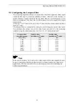
7.4
Wiring of Power Supply and PROFIBUS Data Cable
Wiring of the power supply
The wiring of the power supply (24 VDC) to the terminals in the housing is covered in
the wiring diagram.
Caution
Inadequate earth ground connections may cause electric shock to persons, malfunction
of the total system or damage of the measuring amplifier! It is vital to ensure a good
earth ground connection.
Caution
Improper handling of the amplifier unit may damage the fragile electronic circuitry.
Don’t use rough tools such as screwdrivers or pliers! Handling in the electronic unit
must always take place with the operator using well earthed antistatic bracelets. This
will discharge static electricity of your body before touching the electronic unit!
Wiring of the PROFIBUS cables
The standardized PROFIBUS cable type A
(STP 2x0.34
2
) [AWG 22] has to be used for
the PROFIBUS data cable. The cables are
bared referring to fig. 7 and connected to
the terminals according to the wiring
diagram.
Caution
The shield of the PROFIBUS cable is only grounded if the shield is connected with the
PG gland.
fig. 7: Preparation of the PROFIBUS
cables
E470010e


