background image

FMA Direct 

Co-Pilot II reference manual

If helicopter channels are limited

As initially configured, many CCPM helicopter radio systems 

don’t have a free channel for turning Co-Pilot II on/off and 
selecting Flight Modes.  If your helicopter 

doesn’t

 use four 

channels for flight stabilization (most helis use three servos for 

CCPM) 

and

 doesn’t have enough channels for both gyro control 

and Co-Pilot on/off, there is a solution...

Once adjusted, a variable rate gyro doesn’t need to be changed 
very often.  If Co-Pilot II determines that only three channels are 
being used for CCPM, it can free up the receiver’s gyro channel 
for on/off/Flight Mode use.

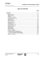
The simplified diagram below shows how the receiver would ini

-

tially be set up to drive the gyro from an auxiliary channel.  This 
arrangement enables you to adjust the gyro from the transmitter, 
and optimize its sensitivity before Co-Pilot II is connected into 
the system.

Receiver

Gyro

Aux

Gyro controlled from transmitter

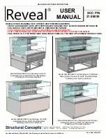
The next diagram shows how the Co-Pilot II Computer fits into 

the system.  The auxiliary channel is used to control Co-Pilot 
through the Computer’s ON/OFF input, while the Computer 

drives the gyro through its SV04 output.  If you turn Co-Pilot II 

off, it continues to drive the gyro.

Receiver

Gyro

Aux

SV04

ON/OFF

Co-Pilot II
Computer

Gyro driven 

by Co-Pilot

Remote control

of  Co-Pilot

When you first program Co-Pilot II, you’ll need to enter the gyro 

sensitivity setting (as a percentage) from your transmitter in the 

“Gyro Output Ch4” screen in the “Preferences” procedure.  If 

you need to readjust the gyro later, just return to the “Prefer

-

ences” screens.

FMA limited warranty

FMA, Inc. warrants this product to be free of manufacturing defects for 
the term of one year from the date of purchase.  Should any defects 
covered by this warranty occur, the product shall be repaired or re-
placed with a unit of equal performance by FMA or an authorized FMA 
service station.

Limits and exclusions

This warranty may be enforced only by the original purchaser, who 
uses this product in its original condition as purchased, in strict ac-
cordance with the product’s instructions.  Units returned for warranty 
service to an FMA service center will be accepted for service when 
shipped postpaid, with a copy of the original sales receipt or warranty 
registration form, to the service station designated by FMA.

This warranty does not apply to:

n

  Consequential or incidental losses resulting from the use of this 

product.

n

  Damage resulting from accident, misuse, abuse, neglect, electrical 

surges, reversed polarity on connectors, lightning or other acts of 
God.

n

  Damage from failure to follow instructions supplied with the prod-

uct.

n

  Damage occurring during shipment of the product either to the cus-

tomer or from the customer for service (claims must be presented 
to the carrier).

n

  Damage resulting from repair, adjustment, or any alteration of the 

product by anyone other than an authorized FMA technician.

n

  Installation or removal charges, or damage caused by improper 

installation or removal.

Call (301) 668-4280 for more information about service and warranty 
repairs.

Updating the Co-Pilot II Computer firmware

Note:

  Internet Explorer must be the default browser during this proce-

dure.

1.  Download the Co-Pilot II updater from 

www.fmadirect.com/downloads.htm


The updater should install automatically.

2.  Launch the updater: 

Start > Programs > FMA Direct > Co-Pilot II 

Update

.

3.  Follow the on-screen instructions.

Special installation considerations

For large aircraft with long servo extensions, or for any aircraft pow-
ered by a gasoline engine, FMA recommends installing the Advanced 
Servo Buffer (Part no. 605SB).  For use with analog and digital ser-
vos, this device:

n

  Filters out electromagnetic interference generated by gas engine 

ignition systems.

n

  Filters out RF interference picked up by long servo wires.

Typical symptoms include erratic servo movement or receiver 
“swamping.”  The Advanced Servo Buffer is 100% effective in elimi-
nating these problems.
1.  Connect the servo wire to the pins toward the bumpy side of the 

Advanced Servo Buffer.

2.  Connect the Advanced Servo Buffer cable to the appropriate servo 

pigtail on the Co-Pilot II Computer.

Advanced Servo Buffer

Servo or servo extension 

connected to pins on bumpy side 

of buffer

Connect to Co-Pilot II 

Computer’s servo output

Summary of Contents for Co-Pilot II

Page 1: ...rared Flight Stabilization System Reference Manual FMA Inc 5713 Industry Lane Suite 50 Frederick MD 21704 Sales 800 343 2934 Technical 301 668 4280 www fmadirect com Instructions for installing setting up and using Co Pilot II ...

Page 2: ...onversion takes place within the sensor modules vir tually eliminating the potential for analog noise in any instal lation Communication between the sensor modules and the Co Pilot Computer Module is sent over standard 3 wire servo connectors 2009 FMA Inc All rights reserved Reproduction of this publication is prohibited Co Pilot is a trademark of FMA Inc U S Patent 6 181 989 Patents held in Germa...

Page 3: ...ll electronic equipment from exposure to rain water high humidity and high temperatures FMA Direct recommends that you join the AMA They can help you find a club in your area Academy of Model Aeronautics 5161 East Memorial Drive Muncie Indiana 47302 Phone 800 435 9262 Web www modelaircraft org Flight stabilization safety precautions Co Pilot II is designed for flight stabilization only It cannot n...

Page 4: ...e differences through a canopy or plastic windows Should be at least 6 inches from other components including the Vertical Sensor Module IRNet Router digital servos ver tical stabilizer horizontal stabilizer and landing gear and at least 12 inches from engine and muffler On fuel powered aircraft should be located where exhaust will not accumulate on the infrared sensors during flights Must be moun...

Page 5: ...the plastic mount The Sensor Module should be rotated 45 relative to the boom i e two Sensor Module corners pointing fore and aft Typically sensors 2 and 3 will face forward so the cable routes forward along the boom Tip For additional security feed cable ties through the slots in the bottom of the Sensor s case and around the boom Main Sensor Module mounted on top of helicopter boom Mounting the ...

Page 6: ...opter Your installation may be different from this Notice that the Main Sensor Module is rotated 45 and mounted in the middle of the boom well away from anything that would block its view of the horizon The Vertical Sensor Module is mounted so that it has a clear view of the sky and ground Vertical Sensor Module Main Sensor Module Co Pilot II Computer Typical helicopter installation the IRNet Rout...

Page 7: ... condition as purchased in strict ac cordance with the product s instructions Units returned for warranty service to an FMA service center will be accepted for service when shipped postpaid with a copy of the original sales receipt or warranty registration form to the service station designated by FMA This warranty does not apply to Consequential or incidental losses resulting from the use of this...

Page 8: ... walls and ceilings n Outdoors especially in direct sunlight range will be short enened and the Programmer will be more directional it will need to be aimed more directly at the Router to get the best reception n To prevent swamping don t aim the Programmer directly at the Router when the two are within 1 2 feet of one another 4 As shown in the Link Up flowchart a Simultaneously press the DEC and ...

Page 9: ...r 3D password Specify Aircraft type Sensor orientation Teach Co Pilot to recognize Up elevator Left aileron Left rudder Enable disable remote on off Specify Off and Flight Mode position s Set Co Pilot trims for Level flight Inverted flight Vertical hover Knife edge flight Specify modulation type Select Remote switch type Set up 2 Way Switch or Volume Knob or 3 Way Switch or Slider Preflight Do Fie...

Page 10: ...puter INC DEC Hold Aircraft on Side or Vertical CHOOSE TASK DO FIELD CALIB Sky to Ground T Diff 20 F GOOD ENTER BACK ENTER Position aircraft nose down nose up or wing down then press ENTER Sky to Ground T Diff 10 F OK Sky to Ground T Diff 9 F BAD Sky to Ground T Diff 7 F OFF Bad weather disables Co Pilot automatically INC DEC ENTER BACK ENTER Main Screens Alternate Screens Computer Decision Operat...

Page 11: ...und T Diff 7 F OFF A E not CENTERED Set Cent Now N A E not CENTERED Set Cent Now Y Weather not Good for ARMING Modes WARNING SYSTEM ERROR Other Error Screens LCD flashes between LCD flashes between ENTER BACK ENTER BACK ENTER BACK ENTER BACK ENTER BACK ENTER Center A E stick on TX then press ENTER ENTER INC DEC Co Pilot II Main Menu CHOOSE TASK PREFLIGHT Preferences Main Menu INC DEC INC DEC Quick...

Page 12: ...es to LEVEL Enable Emergency Recovery N Set Flight Angles N Choose T Units Fahrenheit Show Technical Screens N Disarm Flight Modes to OFF ENTER Enable Emergency Recovery Y ENTER BACK ENTER BACK ENTER BACK ENTER BACK Choose T Units Celsius ENTER Show Technical Screens Y INC DEC INC DEC INC DEC INC DEC INC DEC ENTER Yes No Gyro Output Ch4 100 ENTER BACK Level Flight Roll 0 0 Lf Inverted Flight Pitch...

Page 13: ...type and may not appear Preferences or Main Menu depending on how accessed ENTER BACK ENTER BACK Assigns aerobatic orientation to Flight Mode 2 Some orientations require Vertical Sensor and may not appear Some orientations depend on aircraft type and may not appear Remote On Off Setup Co Pilot learns about TX Remote used to control Co Pilot If Yes TX Remote can be used to turn Co Pilot on off and ...

Page 14: ...o Flight Mode 1 position then press ENTER Remote ON OFF Must move more ENTER This Control has 1 Flt Mode OFF ENTER BACK ENTER BACK If uS change is too small ENTER BACK Select type of TX control used to control Co Pilot Type of Control 3 Way Switch Move Rem ON OFF to OFF Position Move Rem ON OFF to Flight Mode 1 INC DEC Move TX Remote to OFF position then press ENTER Move TX Remote to Flight Mode 1...

Page 15: ...ss ENTER Move Elev Stick Slowly BACK 0 Elevator SAVED Center the Stick Center Aileron and Elevator sticks on TX then press ENTER Pull back Elevator stick on TX Programmer screen must show 98 ENTER ENTER Move Aileron stick on TX to left Programmer screen must show 98 BACK BACK Move Aileron Stk Slowly LEFT 0 Return Elevator stick on TX to neutral then press ENTER Return Aileron stick on TX to neutra...

Page 16: ... calibration number and assures a greater margin over warmer reference terrain Typical infrared temperatures in order from coolest to warm est are snow water grass light vegetation sand and asphalt or concrete If you calibrate over an artificially warm medium such as asphalt or concrete the infrared temperature over anything else will be lower which reduces the temperature difference between earth...

Page 17: ...craft is flying in a narrow valley then high terrain or tall trees on one side will affect the average infrared radiation on that side Take this into account when trimming and flying It s always a good idea to find out how your airplane handles at low speed do this at high altitude This will help you get a feel for how the plane will behave during landing Co Pilot II makes landing much easier by k...

Page 18: ... the helicopter is flying close to the ground variations in ter rain and the resulting infrared signature will cause small variations in trim As you become familiar with the feel of flying with Co Pilot II you ll be able to compensate for these changes almost automatically Here are some examples Your helicopter will hover best over a flat level field Even a slight grade will cause the helicopter t...

Page 19: ...e Earth measured by Co Pilot II provides a more stable and precise reference than light or other phenomena This gives Co Pilot II much more precision than visible light stabilization systems For example Co Pilot II won t cause the aircraft to wander when a cloud comes into view Since the infrared environment is not affected by variations in visible light levels an airplane equipped with Co Pilot I...

Page 20: ...ve a little Typical initial gain settings are n Pitch 70 n Roll 50 You may need to experiment with gain settings to determine what works best for your aircraft and flying style Note If you notice the aircraft is oscillating gain is set too high Land the aircraft and reduce the gain Stick Priority Stick Priority provides a natural flying feel by reducing flight stabilization when you move a stick a...

Page 21: ...of the following attitudes can be assigned to each Flight Mode n Level Flight n Inverted Flight n Knife Edge Flight left wing down n Knife Edge Flight right wing down n Vertical Hover For a helicopter one of the following attitudes can be assigned to each flight mode n Level Flight n Inverted Flight 3D Flight Modes Assign 3D attitudes to Flight Modes in the Quick Setup or Preferences screens Using...

Reviews: