background image

7

❏ 

3. Position the throttle stick (left stick) to idle (all the way 

down) and switch on the transmitter. The power indicator light 
should be glowing a steady red. A fl ashing red light and an 
audible tone indicates low voltage. If this happens, replace 
the batteries before connecting the fl ight battery. 

❏ 

4. Center the aileron, elevator, throttle and rudder trims on 

the transmitter by listening to the beeps. You will hear a low, 
short beep each time you bump the trim. When you hear one 
high, short beep the trim is centered. Experiment running the 
trim to the limits a few times to familiarize yourself with the 
trims. When fi nished, return all the trims to center. 

Before 

connecting the battery to the plane, be sure that you do 
not have the prop installed.

❏ 

5. With the transmitter still switched on, connect the LiPo 

motor battery to the electronic speed control. The motor will 
produce a low tone. Moving the right stick on the transmitter 
up and down will move the elevator on the plane up and down. 
If the motor does not beep and the elevator does not move, 
the receiver will need to be bound to the transmitter. 

❏ 

6. The receiver does not need to be removed from the 

fuselage to bind it to the transmitter. Make sure the throttle 
stick is down in the idle or off position and the transmitter is 
switched on. Insert a small screwdriver or paperclip through 
the hole marked “Bind” and press the pushbutton until the 
LED on the receiver glows red and then turns off after about 
one second. Then, release the bind button. If the binding is 
successful, the LED on the receiver will fl ash once and then 
remain ON.

❏ 

7. Make sure the motor brake function in the ESC is 

deactivated. When you advance the throttle stick, the motor 
should turn. When you bring the throttle stick all the way back 
down, the motor should come to a coasting stop. If the motor 
stops quickly, the brake is on.

❏ 

8. When looking at the motor from the front of the airplane 

the motor should be turning counter-clockwise. If it is not, 
simply unplug any two of the wires from the motor to the 
speed control (ESC) and switch the two wires.

❏ 

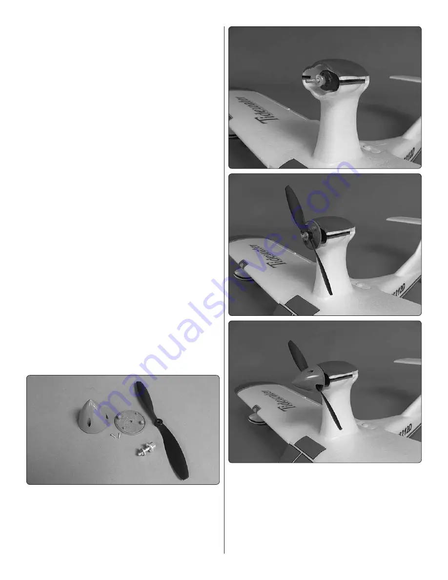
9. Locate the prop adapter, prop, and spinner assembly.

❏ 

10. Slide the prop adapter onto the motor shaft, followed 

by the spinner back plate, the prop, prop washer and prop 
nut. Secure the assembly by tightening the nut to the prop. 
Install the spinner cone over the prop and secure it with the 
two screws that came with the spinner.

Summary of Contents for Tidewater

Page 1: ...ulting liability If the buyer is not prepared to accept the liability associated with the use of this product the buyer is advised to return this kit immediately in new and unused condition to the pla...

Page 2: ...nautics 5151 East Memorial Drive Muncie IN 47302 9252 Ph 800 435 9262 Fax 765 741 0057 Or via the Internet at http www modelaircraft org The R C model hobby becomes more and more enjoyable as your exp...

Page 3: ...ant to get more batteries and an advanced charger so you can charge faster and fly more For the most versatility convenience and faster charging the Great Planes ElectriFly Triton EQ AC DC Charger GPM...

Page 4: ...ng instructions on page 9 Assemble the Fuselage 1 Insert the z bend end of the elevator pushrod wire into the outer hole of the servo arm 2 A brass screw lock connector is pre installed in the bottom...

Page 5: ...screw into the top of the horizontal stabilizer Tighten the screw to secure the horizontal stabilizer to the fin Assemble the Wing 1 Locate the motor pod Install the motor wires through the hole in t...

Page 6: ...o channel 1 in the receiver that is located on the left side of the fuselage under the wing saddle 3 Slide the wing into the wing saddle Secure the wing with the 20 x 2 nylon wing bolt Setting Up the...

Page 7: ...r 6 The receiver does not need to be removed from the fuselage to bind it to the transmitter Make sure the throttle stick is down in the idle or off position and the transmitter is switched on Insert...

Page 8: ...continue to set up the rest of the controls 2 Use the transmitter to make sure all the controls respond in the correct direction 3 Take each screw out of the screw lock connectors on all the pushrods...

Page 9: ...lub site or if you fly somewhere on your own you should always have your name address telephone number and AMA number on or inside your model It is required at all AMA R C club flying sites and AMA sa...

Page 10: ...good way to detect problems that could cause loss of control such as low batteries defective or damaged radio components or radio interference This usually requires an assistant and should be done at...

Page 11: ...commend setting the timer on your transmitter or using a separate timer with an alarm to alert you when it is time to land Electric motors are very reliable but if you fly until the battery cutoff on...

Page 12: ...mitter binds to multiple Tactic 2 4GHz receivers Power status LED built in charge jack TTX404 TRANSMITTER Tx The TTX404 airplane transmitter is available in either a Mode 2 configuration with throttle...

Page 13: ...lane s tail and will rotate the airplane about the yaw axis an imaginary line from the top of the airplane s fuselage to the bottom of the fuselage located near the center point of the fuselage Positi...

Page 14: ...instructions included with the charge kit WARNING It s not recommended to charge batteries at greater than 1 amp through this charge jack Fast charging of NiCd and NiMH batteries should ONLY be done...

Page 15: ...to bind the Tx and Rx together electronically This ensures sole communication between the two and prevents other transmitters from being able to control the receiver 1 Turn on the Tx 2 Apply power to...

Page 16: ...tick result in an equal adjustment of the throttle in the model Depending on whether the airplane is electric or glow powered a Electric confirm that when the throttle stick is at maximum position the...

Page 17: ...in extremely hot or cold locations in direct sunlight or in locations with high humidity Store R C equipment in cool and dry locations Do not allow chemicals to come in contact with any parts of the r...

Page 18: ...ility to dispose of their waste equipment by handing it over to a designated collection point for the recycling of waste electrical and electronic equipment The separate collection and recycling of yo...

Page 19: ...post paid and insured to HOBBY SERVICES Ph 217 398 0007 3002 N Apollo Dr Suite 1 9 00am 5 00pm CST M F Champaign IL 61822 E mail hobbyservices hobbico com This product is suitable only for people of...

Page 20: ......

Reviews: