background image

02

Instruction Steps

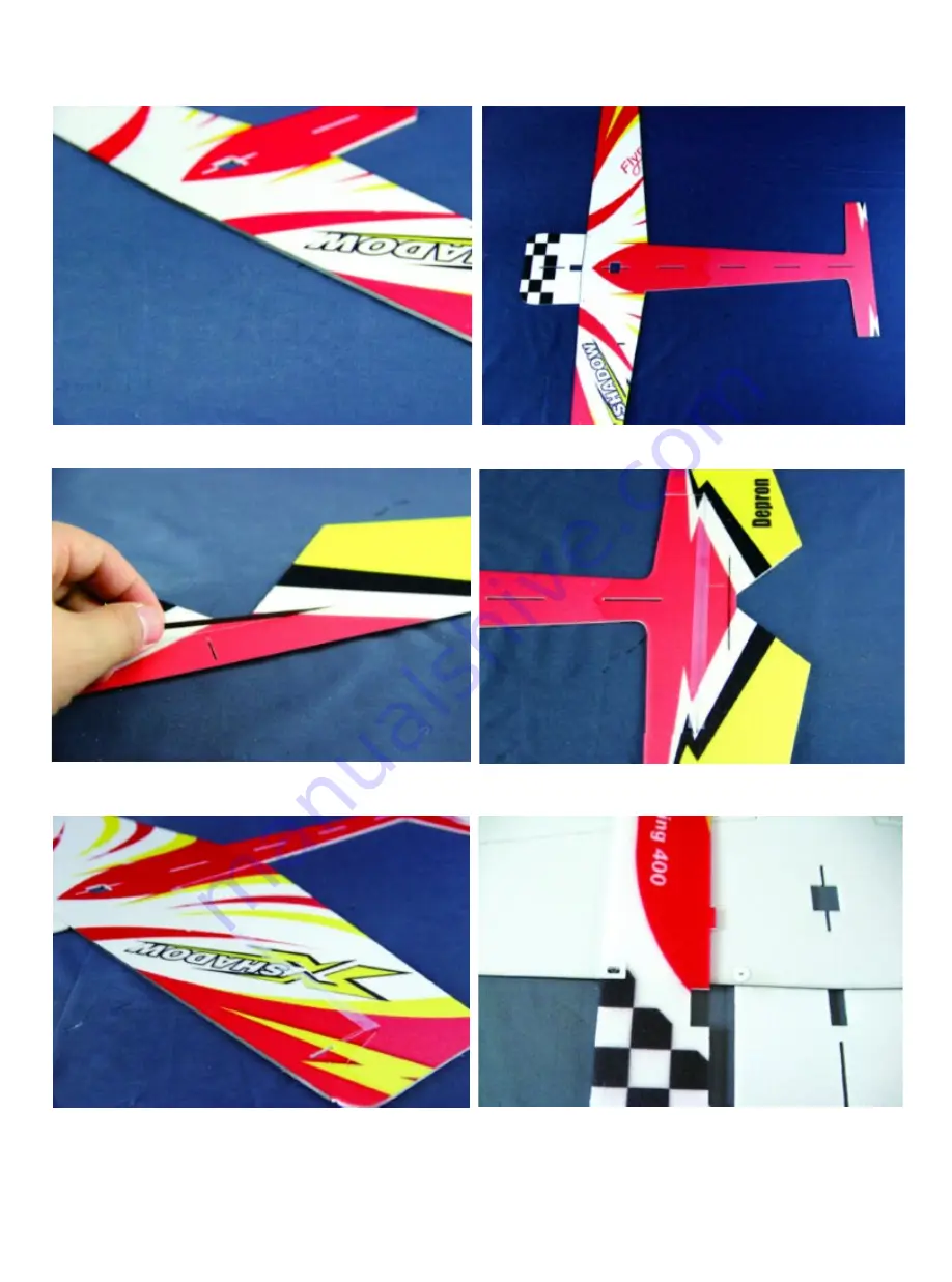
1. Glue the front edge stay bar onto the front edge of the wing.

2.Fix the side fuselage and nose onto the wing with some foam friendly C/A, 

Please make sure they are horizontal, no distortion. 

3.Insert the carbon fiber strip into the pre-cut hole on the horizontal stabilizer.

4.Fix the horizontal stabilizer to the fuselage with 3M magic tape.

5.Fix the aileron to the wing with 3M magic tape.

6.As shown, fix the quadrate and round doublers on the fuselage.

Summary of Contents for Pluswing Series

Page 1: ...vanced technology Shadow is made of Depron Aero the wonderful foam for airplanes models with this ideal material Shadow is very flexible in the air it can achieve many difficult 3D moves The Shadow was reinforced with the best carbon rods so it provides precise and solid feel With flyrace s advanced design Shadow Depron Aero can be easily and quickly built The assembly instruction can help to asse...

Page 2: ...he packing A ABS brackets for push rods B Quadrate and round doublers C Coupling heads D Control horns and servo arms E Landing gear sets F Motor mount G Base of the fuselage stay bar H Velcro 3 Carbon fiber fittings Front edge stay bar 1pcs size 800mm x 3mm x 0 5mm Fuselage stay bar 4pcs size 800mm x diameter 1mm Push and pull rod 2pcs size 600mm x diameter 1mm Wing stay bar 4pcs size 300mm x dia...

Page 3: ... some foam friendly C A Please make sure they are horizontal no distortion 3 Insert the carbon fiber strip into the pre cut hole on the horizontal stabilizer 4 Fix the horizontal stabilizer to the fuselage with 3M magic tape 5 Fix the aileron to the wing with 3M magic tape 6 As shown fix the quadrate and round doublers on the fuselage ...

Page 4: ...ertically on the fuselage 9 Glue the wing reinforcing strips on the wing then place the wing and fuselage press down firmly then put one side of the wing stay bar through the base the other side is fixed on the top of the wing The stay bar should remain straight not buckled 10 Fix the other stay bars on the fuselage as shown in the picture 11 Install the landing gear onto the pre cut holes of the ...

Page 5: ...holes on the fuselage as picture shown 13 Glue the tail fin and two stay bars on the end of lower vertical fuselage 14 Install the Aileron servo arms as the pictures shown 15 Fix the aileron servo with some foam friendly C A then also fix the rudder and elevator servos as picture shown ...

Page 6: ... slots on the aileron with some friendly C A and then fix coupling heads on the aileron servo arms and control horns at last install the aileron push pull rods 19 Glue the fuselage reinforcing strips on the fuselage You can also choose the carbon stay bars to fix the fuselage 20 Insert the control horns into the pre cut holes on the vertical stabilizer and then fix the coupling heads on the rudder...

Page 7: ...with glass fiber tape 21 Insert the control horns into the pre cut holes on the horizontal stabilizer and then fix the coupling heads on the elevator servo arm and control horn at last install the elevator push pull rod 24 Install the motor with the tapping screw and then fix the propeller with the O ring 25 Install the ESC and receiver with Velcro ...

Page 8: ...ghts This will help prevent damage to your model and will speed up the learning process and making your R C experience all the more enjoyable You can contact local R C clubs or your dealer to obtain the names of the experienced R C pilots who would be willing to help you with your first few flights Although this is an ARF Almost Ready to Fly kit it does have some construction features that can be ...

Reviews: