background image

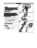
Assembly of Switch Handle to Tube (A1)

Ensure that the internal cable is not twisted.

1. Insert the tube into the switch handle.  
2. Push until it clicks into position.

ENSURE THAT THE TUBE IS FULLY LOCATED BY
ATTEMPTING TO REMOVE IT.

Assembly of Trimmer Head to Tube (A2)

Ensure that the internal cable is not twisted.

1. Insert the tube into the trimmer head.  
2. Push until it clicks into position.

ENSURE THAT THE TUBE IS FULLY LOCATED BY
ATTEMPTING TO REMOVE IT.

Safety Guard Assembly (B1) & (B2)
1. Locate the safety guard over the cutting head.  Ensure

the nylon line is fed through the hole in the safety
guard as illustrated in fig B1.

2. Push into location and turn safety guard in the direc-

tion illustrated in Fig B2, until a click is heard and the
safety guard is securely locked in position.

ENSURE THE SAFETY GUARD IS SECURELY IN
PLACE BY ATTEMPTING TO TWIST GUARD.

Steady Handle Assembly (C)
1. Depress the two buttons on the sides of the switch

handle.

2. Locate the steady handle over the buttons and release

the buttons.

3. Adjust the steady handle to the most comfortable op-

erating position by depressing the buttons and moving
the handle.

Height Adjustment (D)
1. Turn height adjuster (D1) in the direction indicated to

un-lock (D2).

2. Adjust the length of the tube to the most comfortable

operating position.

3. Turn height adjuster in the opposite direction to lock

(D3).

ENSURE THAT THE TUBE IS FULLY SECURED.

Cable Restraint (E1) & (E2)
1. Form loop in mains cable and push the loop through

the slot as illustrated in picture (E1).

2. To secure, position loop over the hook and pull the

cable back through the slot as illustrated in picture
(E2).

Assembly Instructions

B2

B1

C

D

A1

Double Auto Feed System

How the automatic line feed works (F)
1. When initially switching on the trimmer, a small length

of line is fed out.  

2. A ‘clattering’ noise will be heard when the two nylon

lines hit the line cutter.  DO NOT BE ALARMED this is
quite normal. After approximately 5 seconds the line
will be cut to the correct length and the noise will re-
duce as the motor reaches full speed.

Make sure the motor is up to full speed before trim-
ming or edging.

3. If the noise of the nylon line being cut cannot be heard,

more line will need to be fed out.

4. To feed more line, it is first necessary to to allow the

motor to stop completely, then re-start, allowing the
motor to reach full speed.

5. Repeat step 4. until you hear the lines hitting against the

cutter.  (Do not repeat this procedure more than 6 times)

6. If problems are experienced with the automatic line

feed refer to Fault Finding Chart.

F

line cutter

A2

E1

E2

1

3

2

Summary of Contents for Power Trim SET250

Page 1: ...IMPORTANT INFORMATION Read before use retain for future reference Original Instructions ...

Page 2: ...DENTAL STARTING REMOVE PLUG FROM MAINS AND KEEP FEET AWAY FROM THE SWITCH LEVER WHEN CLEANING AROUND THE IN SIDE OF THE SAFETY GUARD REMOVING OR REFIT TING SPOOL CAP MANUALLY FEEDING OR REPLACING NYLON LINE 1 We recommend the use of a Residual Current Device R C D with a tripping current of not more than 30mA Even with a R C D installed 100 safety can not be guaranteed and safe working practice mu...

Page 3: ...normally Check im mediately Excessive vibration can cause injury Maintenance and storage 1 Keep all nuts bolts and screws tight to be sure the trimmer is in safe working condition 2 Replace worn or damaged parts for safety 3 Only use the replacement cutting line specified for this product 4 Only use replacement parts and accessories recom mended by Husqvarna UK Ltd 5 After any maintenance in deali...

Page 4: ...rection indicated to un lock D2 2 Adjust the length of the tube to the most comfortable operating position 3 Turn height adjuster in the opposite direction to lock D3 ENSURE THAT THE TUBE IS FULLY SECURED Cable Restraint E1 E2 1 Form loop in mains cable and push the loop through the slot as illustrated in picture E1 2 To secure position loop over the hook and pull the cable back through the slot a...

Page 5: ...all cuts J 5 Line is fed out automatically every time the trimmer head stops rotating and returns to operating speed Extra line can be fed out manually as described in Manual line feed 6 To stop your trimmer release the switch lever How to edge 1 To convert to edging mode depress the locking button K1 and twist head anti clockwise K2 An audible click will confirm that the head is locked Ensure the...

Page 6: ...d you buy spool and line complete Nylon line only is also available Both are available from Husqvarna UK Ltd stockists To fit spool and line complete 1 Remove the cap 2 Remove old spool 3 Place spool into spoolholder 4 Release one line from cleat Q1 5 Secure line into slot P1 6 Repeat for second line Ensure spool is fully located by gently rotating it during fitment whilst keeping the spoolholder ...

Page 7: ...Disconnect from the mains electricity supply 2 Never clean your trimmer with water cleaning fluids or solvents just remove debris with a suitable tool a soft brush or dry cloth 3 Using a soft brush clean around the inside of the safety guard the cutting head Fig R and the motor housing air vents Fig S 4 Inspect the trimmer carefully especially the parts of the cutting head 5 If your trimmer is dam...

Page 8: ...s not been used for hire g The machine is owned by the original purchaser h The machine has not been used commercially This guarantee is additional to and in no way diminishes the customers statutory rights Failures due to the following are not covered therefore it is important that you read the instructions contained in this Operator s Manual and understand how to operate and maintain your machin...

Page 9: ...3 The maximum A weighted sound pressure level LpA at the operator s position recorded on a sample of the above prod uct s corresponds to the Level given in the table The maximum hand arm vibration weighted value measured according to EN ISO 5349 on a sample of the above product s corresponds to the Value ah given in the table 2000 14 EC The Measured Sound Power LWA Guaranteed Sound Power LWA value...

Reviews: