background image

g

3

S

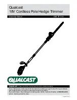
PRODUCT DESCRIPTION  (Fig. 0)

1. Supply cord retainer
2. Rear handle
3. Assist handle lock buttons
4. Air vents
5. Debris shield
6. Cutting line head
7. Edging guide / line protector
8. Motor housing

9. Adjustable shaft

10. Shaft locking button
11. Assist handle
12. On/Off trigger
13. Mains cable

a

SAFETY MARKINGS

The following symbols on your trimmer are intended to remind you of some of the most important
safety precautions:

1. WARNING.

This product is potentially dangerous. Take great care at all times to avoid injury.

2.

Read the operator’s manual.

3.

Disconnect the mains plug if the cord is damaged.

4.

Wear eye protection at all times.

5.

Approved ear defender.

6.

Do not work near bystanders.

7.

Do not use in rain or damp conditions.

8.

LWA indicates the noise power level. Wear ear plugs or mufflers if necessary.

9.

indicates that the product conforms to the relevant European Directives as required by law.

b

ASSEMBLY

DEBRIS SHIELD INSTALLATION

Fig. 2-1

1.

Position the motor housing with string head carrier facing up.

2.

Slide debris shield over motor housing as shown.

Fig. 2-2

3.

Align edging guide with mating grooves and push firmly in the direction shown until an audible
snap is heard.

NOTE: 

Be certain that edging guide is oriented as shown. Once edging guide, motor housing and

debris shield are mated the connection is permanent and cannot be removed without a special tool.

EXCHANGE OF SPOOL

Turn off the machine and disconnect the plug from power supply. Wait until nylonline has come to a
complete stop. Pict. 2-3 Press both press-buttons 

1 and lift off the cover 2. Pict. 2-4 Replace the empty

spool 3 by inserting each line end through the eyelets as shown. Secure the spool with a slight turn to
ensure correct position in the base plate. Then replace the cover ensuring both press-buttons lock in.

NOTE: 

The complete spool and line must be replaced and line must be replaced and is available as

an accessory.

c

PRODUCT ADJUSTMENTS

Fig. 3-1 - Adjustment Assist Handle

1.

Using thumb and forefinger push in both spring loaded lock buttons at the base of the assist
handle in order to release the ratchet adjustment mechanism.

2.

Adjust handle as necessary and release automatic lock buttons.

Fig. 3-2 - Adjust Shaft Length

1.

Grip shaft firmly.

2.

Push red shaft release button forward and move handle forward or backward to desired length.

NOTE: 

Shaft may be adjusted in trimming or edging mode.

Fig. 3-3 - Edging Conversion

1.

Grip shaft firmly.

2.

Push red button forward and rotate handle assembly until an audible click is heard.

Summary of Contents for Power-Trim PN 248722

Page 1: ...ESEN 9 e Manual de Propietario LEER ATENTAMENTE 21 h Gebruiksaanwijzing EERST GOED DOORLEZEN 13 s Ägarhandbok LÄS NOGA 29 q Brugsanvisning LÆS OMHYGGELIGT 32 v Omistajankäsikirja LUE HUOLELLISESTI 38 Eierens Håndbok LES NØYE 35 p Manual de Instruções LER ATENTAMENTE 25 k O HΓIEΣ XPHΣEΩΣ IABAΣTE ΠPOΣEKTIKA 42 Használati útmutató FIGYELEMMEL OLVASANDÓ 46 PN 248722 0 Power Trim Instrukcja obsługi Prz...

Page 2: ...1 17 5 9 21 13 29 32 38 35 25 42 46 8722 1 Ê Â fi fl 0 fi 49 ...

Page 3: ...96dBA 15m 1 2 Fig 2 2 fl fi Fig 2 1 Fig 2 3 Fig 2 4 ...

Page 4: ...3 4 Fig 3 1 Fig 3 3 Fig 4 1 Fig 3 2 4 ...

Page 5: ...lleistu Dauerscha Schwingu d T 230 240 Nullastsne Nullastsne Gewaarbo Gemeten Geluidsdru Trillingsniv h T 230 240 Velocità a Velocità a Livello pot Livello pot Livello reg Livelli di v i D 230 240 Velocidad Velocidad Nivel de p Nivel de p Nivel de p Nivel de v e D 230 240 Velocidad Velocidad Nível potê Nível potê Nível pres Níveis de p E 4 Fig 4 2 Fig 4 3 Fig 4 4 Fig 4 5 Fig 4 6 Fig 4 7 ...

Page 6: ...earing open sandals USAGE 13 Use the trimmer only as described in this manual 14 Check the machine and cable for signs of damage regularly 15 Never use the machine if the guard is damaged or without the guard fitted in place 16 Do not switch the machine on when it is upside down 17 Only switch the machine on when your hands and feet are well away from the head 18 Ensure you maintain a firm footing...

Page 7: ...low WARNING Never wire an extension cable with anything other than the correct female connector and a 13A BS1363A approved plug with a 13 amp fuse Never wire a male connector to your extension cable and never wire an extension cable with a plug of any kind at both ends of the cable This is very dangerous and results in the pins being live which may cause a fatal electric shock PLUG REPLACEMENT If ...

Page 8: ... an audible snap is heard NOTE Be certain that edging guide is oriented as shown Once edging guide motor housing and debris shield are mated the connection is permanent and cannot be removed without a special tool EXCHANGE OF SPOOL Turn off the machine and disconnect the plug from power supply Wait until nylonline has come to a complete stop Pict 2 3 Press both press buttons 1 and lift off the cov...

Page 9: ...e trimmer to sweep debris Fig 4 7 Do not attempt to feed line bumping the head on the ground e ROUTINE MAINTENANCE After usage disconnect from the mains supply and clean dirt and debris from the cutter line area This will prolong motor life by maintaining adequate airflow to cool the motor and ensures the line head continues to snap on and off smoothly Inspect the cutter line head for parts that m...

Page 10: ... registrado 87 dBA Níveis de vibração 3 49 m s2 p ESPECIFICAÇÕES 230 240 V växelström 50 Hz klass II dubbel isolering Tomgångsvarv PW500 9800 min 1 Tomgångsvarv PW700 10100 min 1 Garanterad ljudeffektsnivå LWA 96 dBA Uppmätt ljudeffektsnivå LWA 95 dBA Ljudnivå 87 dBA Vibrationsnivåer 3 49 m s2 s SPECIFIKATIONER 230 240 V vekselstrøm 50 Hz klasse II dobbelt isolering Hastighed uden belastning PW500...

Page 11: ...ási müsorunk következtében a gyártó cég fenntartja a jogát ebben a Használati leirt müszaki adatok elözetes értesítés nélküli változtatására W związku z programem ustawicznego ulepszania swoich wyrobów producenta zastrzega sobie prawo zmiany technicznych szczegółów wymienionych w tej instrukcji bez uprzedniego zawiadomienia BELGIQUE BELGIË Flymo Belgique België Tel 02 363 0311 Fax 02 363 0391 ČESK...

Page 12: ... med de eurpæiske direktiver 98 37 CEE Maskineri direktiv 73 23 EEC Direktiv for lavspænding 93 68 CEE CE mærkningsdirektiv 89 336 CEE EMC direktiv Direktiv 2000 14 CEE Annex VI EU Julistus Vastaavuudesta Allekirjoittanut E C O P I in valtuttaamana vakuuttaa että seuraava tuote Pw500 Pw700 ja jotka on valmistanut E C O P I 23868 Valmadrera LC Via Como 72 Italy on Euroopan direktiivien 98 37 CEE Ko...

Reviews: