Maintenance
RUSKA 2413 — Replacement of Transformer
6
6-5
3.
The feed-thru wires are very brittle and must be treated with the greatest care. Do not
bend these short stubs when exchanging the transformer connecting wires. While
using a 25-watt pencil type soldering iron, lift the transformer connecting wires from
the feed-thru wires. As each wire is lifted, make a note of the wire color and the
socket pin number to which the wire was connected. After the wire is lifted,
continuity may be traced to the correct pin by use of an ohmmeter.
4.
Remove the 2 wires from ground.
5.
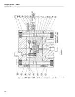
Remove part (14), detent.
6.
Turn the pinion, (12), counterclockwise while preventing transformer from rotating
with the other hand. Do not bend the wires where they are attached to the
transformer. Continue to turn until transformer is free.
7.
Remove the transformer and flush the cell again as in Operation 2. Do not disturb the
core on the diaphragm stem.
8.
Insert the new transformer. The wires may be somewhat longer than the original
ones, but it makes no difference; it is not necessary to shorten them.
9.
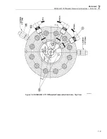
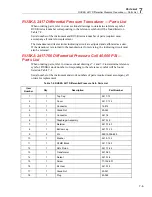
Solder the wires to the terminals following the color code on the diagram (see
Operation 3). Try to prevent oxides and excess flux from dropping into the cavity. If
necessary, flush the cavity when the soldering is complete. Replace the detent.
10.
Make the primary and secondary resistance test.
11.
Plug the box into the mains and allow the circuit to warm up a few minutes.
a.
Set the GAIN to maximum and set the SHUNT switch ON.
b.
Set the ZERO control to midpoint (500 counts).*
c.
Rotate the pinion (12) until the meter indicates zero. Turn the pinion 1/2 to 1
revolution counterclockwise (CCW) and repeat the zero adjustment while
approaching the setting in a clockwise direction. All final adjustments of the
pinion should be made in a clockwise direction to remove the backlash from the
elevating nut threads. The adjustment will then be more permanent.
12.
Wash the cap and bolts and replace the O-ring in the cap if it shows evidence of
extrusion. Do not use a hard metal object to remove the O-ring: use a toothpick or
wooden match.
13.
Assemble the cap and torque the bolts down evenly to 250-foot-pounds.
14.
Connect the box to the transducer. Set gain to maximum, shunt switch OFF and
adjust the meter to zero. Pressing the finger against either of the input ports should
deflect the meter.
* Or to a value that will allow full adjustment of the potentiometer when correcting from
the strain that is given on the calibration report.


