


Calibration Manual
Verification Tests
25
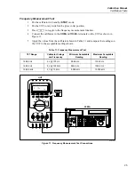
Frequency Measurement Test
1.
Put the calibrator in Standby (
STBY
) mode.
2.
Put the UUT rotary switch in the
K
(ac volts) position.
3.
Press
F
to toggle to the frequency measurement function.
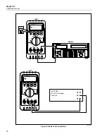
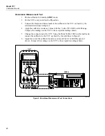
4.
Connect the calibrator to the
COM
and
z
terminals on the UUT as shown in
Figure 11.
5.
Apply the values from the calibrator shown in Table 11 and compare the readings on
the UUT to the acceptable readings shown.
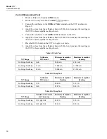
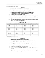
Table 11. Frequency Measurement Test
787 Range
Calibrator Voltage
and Frequency
Minimum Acceptable
Reading
Maximum Acceptable
Reading
199.99 Hz
5 V @ 100 Hz
99.98 Hz
100.02 Hz
1999.9 Hz
5 V @ 1000 Hz
999.8 Hz
1000.2 Hz
19.999 kHz
5 V @ 10 kHz
9.998 kHz
10.002 kHz
OFF
A
mA
COM
V
1000V
30mA
FUSED
0.44A
(1A /30 sec)
FUSED
mA
mA
A
mA
OUTPUT 0-24mA
SOURCE SIMULATE
+
+
% STEP
COARSE
FINE
mV
V
V
OUTPUT
CAT
787
PROCESSMETER
MIN MAX
RANGE
HOLD
H
REL
Hz
UUT
5500A
POWER
I
O
0
•
1
2
3
4
5
6
7
8
9
ENTER
M
k
m
V
Hz
FIELD
EDIT
/
+
F
OPR
EARTH
SCOPE
BOOST
MENU
PREV
SHIFT
RESET
CE
SETUP
REF
NEW
TC
MEAS
¡F
µ
n
p
W
dBm
sec
¡C
A
MULT
x
DIV
÷
OUT
TRIG
5500A CALIBRATOR
20V PK
MAX
HI
LO
TC
TRIG
OUT
1000V
RMS
MAX
20V
RMS
MAX
1V PK
MAX
20V PK
MAX
NORMAL
AUX
SCOPE
V, ,
RTD
A, -SENSE,
AUX V
200V PK
MAX
STBY
LT010F.EPS
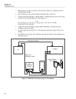
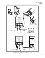
Figure 11. Frequency Measurement Test Connections
Summary of Contents for ProcessMeter 787
Page 2: ......
Page 4: ...Model 787 Calibration Manual ii ...
Page 6: ...Model 787 Calibration Manual iv ...


