Service Information Sheet for Serial Numbers < 79370000
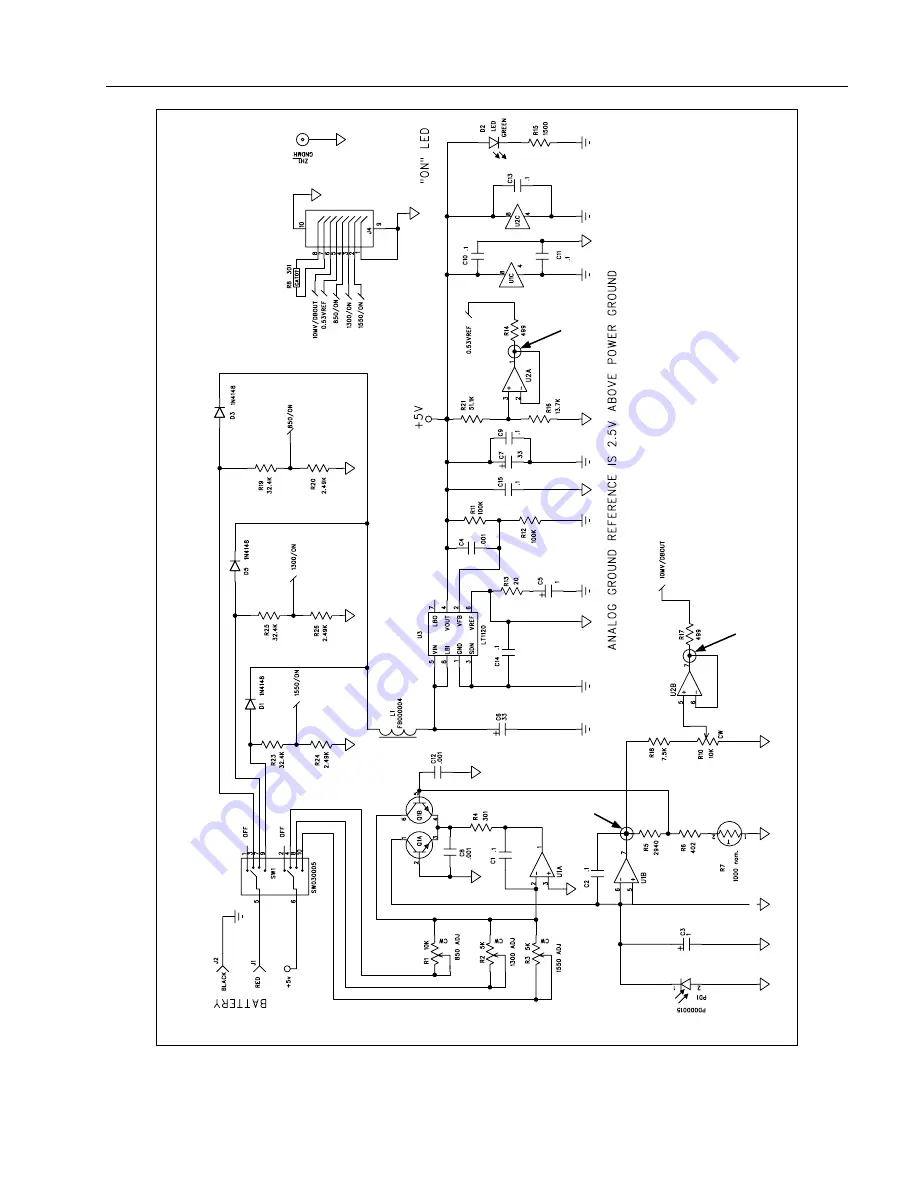
Fiber Optic Meter Schematic for SN
<
79370000
7
FPM2-00-0300
DB
out
V
ref
det
Dt11f.eps
Figure 1. Fiber Optic Meter Schematic for SN
Page 1: ...ents Parts and accessories lists Schematic Diagram showing calibration measurement and adjustment points For operating instructions refer to the DSP FOM DSP FTK Fiber Optic Accessory Instruction Sheet...
Page 2: ...the selected wavelength and a full scale voltage reference for determining the battery status Switch Positions and I O Slide switch SW1 is a 2 pole switch One pole pin 5 applies the battery voltage t...
Page 3: ...2 required 2 m UTP patch cable supplied with the CableMeter test tool Performance Tests Use the performance tests to confirm that the FOM is working properly If the FOM fails any of these tests clean...
Page 4: ...n While servicing the FOM always follow guidelines for preventing electrostatic discharge ESD Otherwise ESD can damage sensitive components causing immediate or delayed failure of the FOM A Phillips h...
Page 5: ...tput to the reference power meter Set the attenuator output to 45 dBm 0 1 dBm Record the value shown on the reference power meter as Pin for step 3 3 3 2 Connect the attenuator output to the FOM 3 3 U...
Page 6: ...djust R3 for Vo as calculated in step 5 4 0 0005 V Step 6 Verifying Calibration 6 1 Follow the procedures given in the earlier section Performance Tests 6 2 Apply insulating varnish such as red GLPT t...
Page 7: ...Service Information Sheet for Serial Numbers 79370000 Fiber Optic Meter Schematic for SN 79370000 7 FPM2 00 0300 DB out V ref V det Dt11f eps Figure 1 Fiber Optic Meter Schematic for SN 79370000...
Page 8: ...DSP FOM Fiber Optic Meter 8 FPM2 00 0001 Pin 7 Pin 5 Pin 1 Pin 7 Dt14f eps Figure 2 Calibration Measurement and Adjustment Points for SN 79370000...