Flowserve Gestra GAV 56F Installation Instructions Manual Download Page 16


Troubleshooting 

Problem Cause  Remedy 

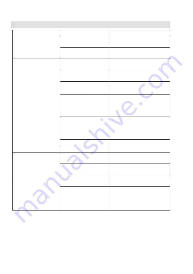
Insufficient flowrate 

The equipment is not 
completely open.

Completely open the equipment 

The sealing plugs have not 
been removed.

Remove the equipment. Take off the 
sealing plugs. Mount the equipment.

Fluid escapes (equipment is 
leaking). 

The end connections are not 
tight.

Insulate the connections. 

A gasket on the body is 
defective.

Replace the equipment with a new one. 

Leakage occurs at the stem, 
the bellows is damaged. 

Re-tighten the stuffing box packing. 
Replace the equipment with a new one. 

The body has been damaged 
by corrosion or erosion. 

Check the resistance of the material for 
the fluid used. 
Use a device made from a material that 
is suitable for the fluid used. 

The equipment has been 
damaged by frost. 

Replace the equipment with a new one. 
When shutting down the installation 
make sure that all lines and the 
equipment are completely drained. 

The plug or seat is damaged.

Replace the equipment with a new one. 

The seat is leaking.

Excessive force is needed to 
turn the handwheel. 

The locking screw has been 
tightened.

Loosen the locking screw. 

The position of the stroke 
limiter is fixed by a locknut.

Loosen the locknut of the stroke limiter. 

The stem is insufficiently 
lubricated.

Apply lubricant to the stem. 

Limit stop has been reached. 

You can only turn the handwheel up to 
the stop. 

Turn the handwheel into the other 
direction. 


If faults occur that are not listed above or cannot 
be corrected, please contact our Technical 
Service or authorized agency in your country. 

16  

Summary of Contents for Gestra GAV 56F

Page 1: ...Shut Off Valve GAV 56F Original Installation Instructions 819237 01...

Page 2: ...reparing installation 9 Connecting the equipment 10 Retrofitting and adjusting a stroke limiter 12 Operation 13 Activities during operation 13 After operation 13 Changing the settings 14 Removing exte...

Page 3: ...al is available to the operator The installation operating manual is part of the equipment Please hand over this installation operating manual when selling the equipment or passing it on Text layout C...

Page 4: ...acquainted with and experienced in the following Making pipe connections Selecting suitable lifting gear and understanding the rules for its safe use Working with dangerous contaminated hot or pressur...

Page 5: ...elivered packed and ready for assembly WARNING Notes with the heading WARNING warn against possibly dangerous situations that could lead to death or serious injuries CAUTION Notes with the heading CAU...

Page 6: ...Equipment specification 3 4 6 7 8 11 12 13 10 9 1 2 5 6...

Page 7: ...this type of plug can only be used for shutting off the pipeline This installation manual shows equipment with throttling plug A stroke limiter is available as optional extra End connections The equip...

Page 8: ...s In addition equipment DN 15 up to DN 100 can also throttle the flowrate Function The equipment is designed for shutting off pipelines For this purpose equipment types DN 125 and DN 150 are fitted wi...

Page 9: ...the equipment Prior to transport seal off connections with sealing plugs If you do not have the sealing plugs supplied with the equipment use appropriate seal caps to seal off the connections For shor...

Page 10: ...e sure that the flow arrow on the equipment body matches the direction of flow in the pipe Specialist personnel must be highly qualified and fully experienced in making pipe connections for the respec...

Page 11: ...pen and close the valve several times After putting the equipment into operation make sure that neither the equipment nor any connections leak Should you encounter any leaks please proceed as follows...

Page 12: ...the flowrate A commercial grade hexagon bolt with nut serves as stroke limiter The size of the hexagon bolt and nut depends on the equipment type The required hexagon bolt and nut are commercially av...

Page 13: ...in your plant Do not work on the equipment while it is operating After operation DANGER If the equipment is used in contaminated areas there is a risk of severe injuries or death caused by harmful su...

Page 14: ...sed to throttle the flowrate CAUTION Hot surfaces and heat radiation present the risk of burns Wear protective gear that is suitable for the temperatures generated in your plant Wear protective gloves...

Page 15: ...move any persistent residues use a cleaning agent that is suitable for the material and carefully wipe the equipment with a clean lint free cloth Maintaining the equipment Servicing the equipment and...

Page 16: ...om a material that is suitable for the fluid used The equipment has been damaged by frost Replace the equipment with a new one When shutting down the installation make sure that all lines and the equi...

Page 17: ...ntil no more fluid escapes 13 DANGER Personnel working on pipes are exposed to safety risks and may suffer severe injuries poisoning or even loss of life Make sure that no hot or hazardous fluid is in...

Page 18: ...ng the hazardous substances in question Qualified personnel must have extensive experience with and a working knowledge of pertinent rules and regulations concerning handling hazardous substances spec...

Page 19: ...ing if the equipment falls down When removing the equipment make sure the it is safely held in place and cannot fall down Suitable measures are for instance Equipment that is not too heavy may be supp...

Page 20: ...ulations concerning waste disposal The equipment is made from the following materials Component DIN EN Handwheel up to DN 80 Steel plate with epoxy coating Handwheel DN 100 up to DN 150 Nodular cast i...

Page 21: ...mm 125 125 125 125 150 150 Lift mm 6 5 6 5 8 0 8 0 14 0 14 0 Weight kg 4 6 4 9 6 5 7 5 11 0 13 0 Overall length to EN 558 series 1 Dimensions and weights for DN 65 to DN 150 DN mm 65 80 100 125 150 DN...

Page 22: ...DN 150 DN mm 65 80 100 125 150 DN inch 2 3 4 5 6 value 5 7 5 5 5 7 5 2 5 0 KVSvalue m3 h 71 109 167 280 409 Pressure temperature ratings Pressure temperature limits DN 15 to DN 150 p pressure bar 40...

Page 23: ...load the current Declaration of Conformity or Declaration by Manufacturer go to www gestra com documents or contact Manufacturer GESTRA AG P O Box 10 54 60 D 28054 Bremen Telephone Fax E mail Internet...

Page 24: ...flowserve com Web www flowserve com Singapore USA Flowserve Pte Ltd Flowserve GESTRA U S 12 Tuas Avenue 20 2341 Ampere Drive Singapore 638824 Louisville KY 40299 Tel 0065 68 79 89 00 Tel 001 502 267...

Reviews: