background image


6.    Connect supply air to port marked “S”. 


7.  Connect instrument signal air to the port marked “I” for model 7000 and 7600. For models 7100, 7200, or 7500, 

connect 4-20 mA and ground (-). For intrinsically-safe applications (Model 7400 only), see separate intrinsically-safe 
I/P IOM for barrier requirements and schematics. The I-P is factory calibrated and cannot be adjusted.  


8.  Stroke actuator/valve two or three times to align positioner, coupler and actuator. With 50% input (actuator at 45 

degrees), tighten all mounting bolts. Stroke actuator/valve again to verify there is no misalignment throughout stroke.  


Calibration:  
 

The unit is shipped from the factory pre-calibrated for 90 degree travel (±0.5 degrees rotation – can also be 30/45/60 
degrees, see installed cam). For most applications, the valve closed position is much more critical than the valve open 
position. Most attention should be made to the valve closed position. Always start calibration procedure by applying 
0% input signal, then adjusting zero position.  
 

Caution: Cam pinch points may injure fingers. Be sure to avoid placing fingers and other objects in cam pinch points. 
Also avoid touching balance bean and spool while making adjustments as an unpredictable cam rotation may result. 
Finally, maintain control of input signal while making adjustments. 

After mounting the positioner on the actuator, check cam setting and if needed, perform a cam adjustment: 

 
  After mounting the position on the actuator, check cam setting and if needed, perform a cam adjustment: 
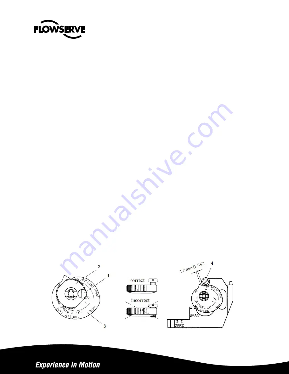


Cam Adjustment: 


1.  Remove cove and indicator. 


2.  Loosen the screw (1) and turn the cam locking nut (2) counter-clockwise until the cam loosens.  


3.  Adjust the cam (3) as desired making sure that the ball bearing (4) is riding on an active lobe on the cam. 


4.  To secure the cam, make sure that the screw (1) is backed out form the locking nut (2) then finger tighten the 

locking nut and tighten screw (1). 


5.  Install and adjust the indicator and re-install cover. 


Summary of Contents for APEX 7000

Page 1: ...cations dew point 18 degrees below ambient temperature particle size 5 microns oil content 1ppm Mounting The following instructions apply to rotary actuators only Linear applications require special m...

Page 2: ...e made to the valve closed position Always start calibration procedure by applying 0 input signal then adjusting zero position Caution Cam pinch points may injure fingers Be sure to avoid placing fing...

Page 3: ...etting by turning screw C while doing so keep the zero screw B in position by applying pressure with your thumb 8 Lock the calibration mechanism in place by tightening locking screw A 9 Apply 0 signal...

Page 4: ...w Figure below shows cam setting for Direct Action increasing signal 0 1005 20 100 kPa 3 15 psi to open Cam follower to ride on lobe D 0 100 Figure below shows cam setting for reverse action decreasin...

Page 5: ...nce arm 5 engage the slot in spool 6 3 Tighten screw 1 4 Check for smooth operation of assembly I P Installation All I O modules are factory calibrated an cannot be adjusted Kits are available to allo...

Page 6: ...es 1 See hazardous location certificate for detailed temperature ratings All Apex 7000 units comply with ATEX directive for non electric equipment intended for use in hazardous locations to Ex II 2 G...

Page 7: ...equipment See Supply Air Requirements 2 Make sure arms bearings and adjustment screws move freely Caution Moving parts to check freedom with supply pressure connected will cause rotation of cam Be sur...

Page 8: ...y 7 1 Feedback spring 6 30 psi assembly Green 8 1 Lower arm assembly 9 1 Rod 10 1 Spring 11 1 Twist Stop 12 1 Pilot valve incl O rings 13 1 Cam locking nut incl screw 15 1 Mounting adapter incl screws...

Page 9: ...necting block NPT assembly 3 1 Connecting block G assembly 4 1 Relief valve spring 6 1 Gasket for Apex 7000 6 1 Gasket for Apex 7100 7 1 Diaphragm cover incl O ring 8 1 Diaphragm 9 2 Diaphragm washer...

Page 10: ...PT 1 8 36 4 Plug 1 8 G 37 1 Cam 38 45 75 80 1 Screw set Apex 7000 7100 6 46 53 67 70 75 80 1 O ring set Apex 7000 7100 Nitrile NBR 6 46 53 67 70 75 80 1 O ring set Apex 7000 7100 Silicone Q 54 1 Spind...

Page 11: ...purchaser user must therefore assume the ultimate responsibility for the proper sizing and selection installation operation and maintenance of Flowserve products The purchaser user should read and und...

Reviews: