|
2
MN30410 Rev A
Introduction / Table of Contents
Step One
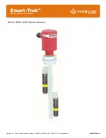
The general purpose level switch package provides automatic tank filling and emptying up to 10’ (3m) between
two adjustable level switch points. The compact level controller with optional strobe alert provides one latching
16A relay for pump or valve control. Offered in three level sensor technologies, select the type based upon
your application media. This polypropylene liquid level switch package is widely selected for sump, process
and day tank level applications.
FEATURES
Fail-Safe relay control of pumps, valves or alarms with a 0 to 60 second delay.
Offered in three sensing technologies for broad application coverage: ultrasonic vibration & buoyancy.
Polypropylene enclosure rated NEMA 4X with swivel base for conduit alignment.
Easy setup with LED indicators for sensor(s), power and relay status.
Invert switch changes relay state from NO to NC without rewiring.
AC
powered
TABLE OF CONTENTS
Specifications/Dimensions: ............................................................................................... 3
Parts
Included:
......................................................................................................
4
Configurations:
......................................................................................................
5
Safety Precautions: ........................................................................................................... 6
Make a Fail-Safe System: ................................................................................................. 7
Getting Started: ................................................................................................................. 8
Features of Controller (Latch ON or Latch OFF): ................................................. 8
Guide to Controls: ................................................................................................. 7
Electrical: ........................................................................................................................ 10
VAC Power Input Wiring: .................................................................................... 10
Relay Input Wiring: .............................................................................................. 10
Strobe Alert Output: ............................................................................................ 10
Automatic Fill / Empty: ........................................................................................ 11
Changing from 120 to 240 VAC: ......................................................................... 12
Assembly of Smart Trak™: ............................................................................................. 13
Sensor
Location:
.................................................................................................
14
Smart Trak™ Assembly: ..................................................................................... 15
Assembly of Switch Car: ................................................................................................. 16
Installation: ...................................................................................................................... 17
Maintenance: .................................................................................................................. 18
Controller
Logic:
..................................................................................................
18
Troubleshooting
..................................................................................................
19
Warranty ......................................................................................................................... 20


