LM900006 Rev 0_3
13
|
Assembly of Smart-Trak™
Step
Six
ABOUT SMART TRAK™:
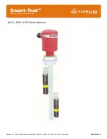
Flowline’s Smart Trak™ with Compact Relay Controller Assembly is an adjustable mounting system for
installing two level sensors vertically within a tank. Mounted through a single point at the top of the tank, both
sensors can be adjusted in the field. The compact relay controller features a 120/240 VAC latched controller
with a 250 VAC, 10A SPDT relay contract. Smart Trak™ mounts vertically through a standard 2" NPT tank
adapter or on a side mount bracket (such as the LM50-1001). Unlike prefabricated “trees” or pipes, Smart
Trak™ allows you to experiment with sensor position to account for variations in the point of actuation of each
sensor during process testing.
TRACK:
The track itself is approximately 1" square, and is from 8” to 10' long depending on
the A-Dimension. The track may be cut to length if desired. Four separate grooves
run the length of the track, one on each side of the square. These grooves hold
the sensor cars that attach to Flowline sensors, and also serve to contain the
switch cable. The bottom of the track is capped with an end cap.
RELAY CONTROLLER:
Both level switches are pre-wired before shipment to the 4-pole terminal strip
[Input 1A (+) & (-) & Input 1B (+) & (-)]. The switch technologies used to indicate
level are either Ultrasonic, Buoyancy or Vibration. The Compact Relay Controller
provides a 1/2” Conduit connection and 6 poles for wire termination of power and
relay contact. Use the AC, AC and GND terminals for providing power. Use the
NC, NC and COM terminals for interfacing to the relay contact.
Compact Relay Controller
(inside shown)
VIBRATION (LZ12-1405) WIRE CONFIGURATION:
Typically applied in wastewater media with light
coating and/or foaming characteristics. Use only
the Red and Black wires.
White, Green and
Yellow wires are not used.
ULTRASONIC (LU10-1305) WIRE CONFIGURATION:
Broadly applied in chemical, solvent, hydrocarbon
and light weight oil media. Use only the Red and
Black wires.
White and Green wires are not used.
BUOYANCY (LV10-1301) WIRE CONFIGURATION:
Best applied in clean water or water-like chemical
media that is non-coating or scaling. Use the
White and Black wires for a Normally Open switch.
The Red and Black wires can be used for a
Normally Closed switch.


