


Installation and Maintenance Manual
Series 19 - Segmented Ball Valves
Date: Feb 2013 / Page 6 of 19
Installation and Maintenance Manual
Series 19 - Segmented Ball Valves
Date: Feb 2013 / Page 7 of 19
®
®
A Subsidiary of BRAY INTERNATIONAL, Inc.
A Subsidiary of BRAY INTERNATIONAL, Inc.
FLOW-TEK, Inc.
Tel: 832.912.2300
© 2012 Flow-Tek, Inc.
8323 N. Eldridge Pkwy #100
Fax: 832.912.2301
Houston, Texas 77041
www.flow-tek.com
FLOW-TEK, Inc.
Tel: 832.912.2300
© 2012 Flow-Tek, Inc.
8323 N. Eldridge Pkwy #100
Fax: 832.912.2301
Houston, Texas 77041
www.flow-tek.com
6. PREVENTATIVE MAINTENANCE
UÊ
At least once every six months, check for proper
operation by following the preventative maintenance
steps outlined below. These steps may be performed
while the valve is in line and without interrupting service.
If an internal problem is suspected, refer to section
“9”
for class 150/300 and “11” for class 600
.
UÊ
Look for signs of gasket leakage through the end flanges
and post. If necessary, re-torque end flanges and post
cover.
UÊ
Examine the valve for damage caused by corrosive
fumes or process drippings.
UÊ
Clean the valve and repaint areas of severe oxidation.
UÊ
Check the packing-box for proper tightness. If there is
a persistent leak, change the packing after referring to
sections
“9.3” class 150/300 and “11.2” class 600
for dismantling the valve, “9.5” class 150/300 and
“11.3” class 600 for Reassembling the valve.
CAUTION:
Do not over tighten packing. This can cause
excessive packing wear and high friction that may
impede stem movement.
UÊ
If the valve is equipped with a lubricator, add lubricant
if necessary.
UÊ
If possible, stroke the valve and check for smooth, full
stroke operation. Unsteady stem movement may indicate
an internal valve problem.
UÊ
Check the calibration of the positioner/controller if
available. For further preventative maintenance, see the
instructions in the installation, operation and maintenance
manual for the applicable positioner/controller.
UÊ
Ensure all accessories, brackets and bolting are securely
fastened.
UÊ
If possible, remove power source (air supply/electrical
signal) and observe actuator for correct fail-safe action.
UÊ
Check the actuator and all air connections for leaks.
UÊ
If an air filter is supplied, check and replace the cartridge
if necessary.
Table 1:
Flange Bolting Specifications
Size
(in)
ANSI
CLASS
RATINGS
Bolt Length
(mm)
(2)
Torque (N-m)
(1)
Low
Strength
Intermediate
Strength
1
150
65
31
82
300
75
63
165
600
90 / 80
(3)
63
165
1
½
150
70
31
82
300
90
110
295
600
110 / 90
(3)
110
295
2
150
85
63
165
300
90
63
165
600
110 / 95
(3)
63
165
3
150
90
63
165
300
110
110
295
600
125 / 110
(3)
110
295
4
150
90
63
165
300
115
110
295
600
145 / 125
(3)
179
478
6
150
100
110
295
300
120
110
295
600
170 / 150
(3)
270
720
8
150
110
110
295
300
140
179
478
10
150
115
179
478
300
160
270
720
12
150
120
179
478
300
170
401
1069
(1) Torque values are recommended for low and intermediate strength
bolting per ANSI B16.5 ¶5.3.2. Higher torques may be used with high
strength bolting (ANSI B16.5 ¶5.3.1). In all cases the user must verify the
selected bolting‘s ability to seat the joint under expected operating condition.
Long thru-bolted joints generally require higher strength bolting and torque
values than shorter flanged bolting depending on operating conditions.
(2) Lengths are based on ANSI B16.5 stud bolts and raised face ends.
(3) Lengths are for the shorter studs used in treaded holes. Refer General
Assembly drawing for the quantities.
7. REMOVING VALVE FROM LINE
1. If an internal problem is suspected with the valve and
disassembly is required, remove the valve from the line
by proceeding as follows.
WARNING:
Depressurize line to atmospheric pressure,
drain all process fluids and decontaminate the valve (if
caustic or hazardous materials are present). Failure to
do so can cause serious injury. Make sure the valve is in
closed condition.
2. Attach a hoist or some means to support the valve.
3. Remove line bolting. Do not attempt to pry line flanges
apart by pushing or pulling on the valve or actuator.
4. Slide the valve carefully from the line. To avoid damage
to the gasket surfaces, do not twist the valve.
5. After the valve is completely removed from the line,
slowly relieve air pressure from the actuator.
8. ACTUATOR
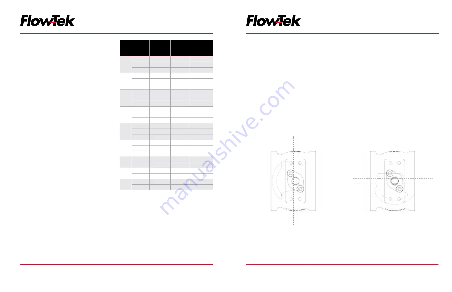
The valve closed and open position are indicated by the
position of double “D” on the stem. Refer below figure.
If possible, install the valve so that the actuator can be
disconnected without removing the valve from the piping.
The actuator must not touch the pipe line, because pipeline
vibration may damage it or interfere with its operation.
In some cases, for instance when a large-size actuator is
used or when the pipe line vibrates heavily, supporting the
actuator is recommended.
Figure 1
CLOSED
CLOSED
OPEN
OPEN


