background image

FLIR


MR160


USER


GUIDE


Document


Identifier:


MR160

en

US_AA


13


5.2.6


External


Moisture


Probe


(Pin)


Measurements


1. Follow


the


steps


in


Section


5.2.1


through


5.2.4


and


select


Pin


mode


from


the


MOISTURE

mode


options.


2. Connect


the


external


pin


probe


to


the


meter’s


EXT


jack


on


the


bottom


of


the


meter

(under


the


protective


flap).

3. Select


the


appropriate


Material


Group


as


described


in


Section


5.2.4


(see


Section


9


for


the

Material


Group


Appendices).


Note:


Use


Group


9


for


building


materials.

4. Press


the


pins


into


the


material


under


test.


5. The


moisture


reading


is


displayed


on


the


main


display


(in


%WME)


in


the


upper


left


hand

corner


(IR


+


Moisture


mode)


or


as


a


bargraph


with


accompanying


digits


(Moisture

only

mode).


Refer


to


example


screens


shown


in


Fig.


5

1


and


Fig.


5

2.


5.2.7


Reference


Mode


Moisture


Measurements


1. Follow


the


steps


in


Section


5.2.1


through


5.2.4


and


select


SET


REFERENCE


from


the

MOISTURE


mode


options.


This


mode


is


only


available


for


pinless


measurements


(internal

sensor).

2. When


the


SET


REFERENCE


mode


is


selected


a


new


display


line


will


appear


preceded


by


a

delta


(triangle)


symbol.


The


digits


next


to


the


triangle


symbol


indicate


the


reference


value

(the


measurement


recorded


when


the


SET


REFERENCE


mode


is


selected).


Refer


to

example


screens


shown


in


Fig.


5

1


and


Fig.


5

2.


3. All


measurements


taken


subsequently


will


be


relative


to


the


reference


value.


For

example,


if


the


reference


value


is


‘10’


(representing


the


driest


area


of


the


material


under

test)


and


a


measurement


of


‘50’


is


taken


(in


an


area


with


higher


moisture


content),


the

measurement


line


will


show


‘40’


(50


10


=


40).


As


implied,


this


mode


is


useful


for

comparing


wet


areas


to


a


dry


area


reference.


4. The


reference


value


is


displayed


on


the


main


display


in


the


upper


left


hand


corner


(IR


+

Moisture


mode)


or


to


the


right


of


the


bargraph


(Moisture

only


mode).


Refer


to


example

screens


shown


in


Fig.


5

1


and


Fig.


5

2.


5. To


remove


the


reference


value


and


exit


the


mode:


Remove


the


meter


sensor


from


the

area


under


test,


so


that


the


sensor


is


no


longer


touching


a


surface


and


is


clear


of


any

objects


(keep


hands


away


from


the


sensor


also),


and


then


press


the


Set


Reference


icon

again.


The


reference


value


will


no


longer


be


visible


on


the


meter


display.

Summary of Contents for MR160

Page 1: ...USER MANUAL FLIR MODEL MR160 IMAGING MOISTURE METER 99 Washington Street Melrose MA 02176 Phone 781 665 1400 Toll Free 1 800 517 8431 Visit us at www TestEquipmentDepot com...

Page 2: ...u Icons Overview 9 5 OPERATION 10 5 1 Powering the Meter 10 5 1 1 Auto Power OFF APO 10 5 2 Moisture Measurements and Display Overview 10 5 2 1 Moisture Measurement Overview 10 5 2 2 Display Overview...

Page 3: ...Waste 19 7 SPECIFICATIONS 20 8 TECHNICAL SUPPORT 21 9 MATERIAL GROUPS 22 9 1 Common Names of Timbers BS888 589 1973 with MR160 Group Nos 22 9 2 Botanical names of timbers with MR160 program group num...

Page 4: ...ein are used for identification only and are the property of their respective owners 1 2 Quality Assurance The Quality Management System under which these products are developed and manufactured has b...

Page 5: ...cautions and notes FLIR Systems reserves the right to discontinue models parts or accessories and other items or to change specifications at any time without prior notice 2 2 Laser Safety Warning Sta...

Page 6: ...proper use will provide years of reliable service 3 1 Key Features FLIR Lepton microbolometer Focal Plane Array FPA with integrated shutter delivers best in class thermal imaging Quickly indicate the...

Page 7: ...ure button 3 Four 4 Navigation buttons rim 4 Select button center 5 Back button 6 Laser Pointer Cross hairs button 7 Power button 8 Ext Probe jack USB port Charging LED 9 Laser pointer lens back 10 Th...

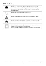
Page 8: ...erface to transfer images to computer or other compatible device Press to back out of return from a menu screen Press to activate laser pointer cross hairs in thermal imaging modes Press to power the...

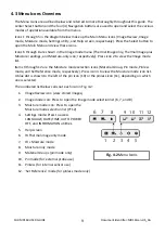
Page 9: ...mode list Items 9 through 12 are the Moisture mode selection icons Material Group Pin mode Pinless mode and Set Reference mode respectively Press icon 3 to view the Moisture mode icon list A blue dot...

Page 10: ...sensor rear or by connecting an external pin probe NOTE Objects in close proximity to the internal pinless moisture sensor located on the rear of the unit will affect the reading on the display Keep...

Page 11: ...ser pointer ON OFF 8 Moisture reading digital format 9 Moisture reading bargraph format appears blue when in non Alarm state 10 High Moisture Alarm setting see Sections 5 4 and 5 7 11 Set Reference va...

Page 12: ...ensor Note the pinless icon 4 on the upper left of the main display when selected 5 SET REFERENCE MODE SET REFERENCE is used to compare the displayed readings against a stored reference measurement se...

Page 13: ...FERENCE mode is selected a new display line will appear preceded by a delta triangle symbol The digits next to the triangle symbol indicate the reference value the measurement recorded when the SET RE...

Page 14: ...ard the area of interest and view the image on the meter display Hot to cold temperatures for images are represented by this color palette progression white grey black blue white See the color palette...

Page 15: ...Laser button to activate 2 Battery status icon is visible when a program menu is accessed 3 IR Thermal Image 4 Cross hairs Press Laser button to activate 5 Tool tips 6 Image mode icons row IR Thermal...

Page 16: ...to switch the alarm ON OFF Refer to Section 5 7 for Alarm mode details The Alarm can be used in pin or pinless mode of operation Press the Select button to save the value and return to the SETTINGS m...

Page 17: ...e Mode 2 Hold the Capture button until crosshairs appear and laser are visible Fig 5 8a 3 While continuing to hold the Capture button aim the laser at the measurement spot 4 Release the Capture button...

Page 18: ...the Select button to return to the SETTINGS mode and save the value or press the back button to cancel and to return to the normal operating mode 6 When the High Alarm is set ON the main display will...

Page 19: ...port is located on the bottom of the meter under the protective flap next to the EXT Probe jack 3 While the meter is charging a blue LED bottom of meter under protective flap indicates that charging i...

Page 20: ...sampling rate 2 samples per second Internal memory 4GB Power supply 3000mAh 2 x 1500mAh Li ion rechargeable batteries Battery life 10 hours minimum Auto Power OFF Programmable OFF 1 5 or 20 minutes L...

Page 21: ...FLIR MR160 USER GUIDE Document Identifier MR160 en US_AA 21...

Page 22: ...ga 1 Kauri Queensland 8 Pine Nicaraguan Pitch 3 Basswood 6 Keruing 5 Pine Parana 2 Beech European 3 Kuroka 1 Pine Ponderosa 3 Berlina 2 Larch European 3 Pine Radiata 3 Binvang 4 Larch Japanese 3 Pine...

Page 23: ...ey Bark 2 Oak American White 1 Sterculia Brown 1 Elm Rock 4 Oak European 1 Stringybark Messmate 3 Elm White 4 Oak Japanese 1 Stringybark Yellow 3 Empress Tree 8 Oak Tasmanian 3 Sycamore 5 Erimado 5 Oa...

Page 24: ...sungulis 1 Fraxinus excelsior 1 Pipadeniastrum africanum 1 Araucaria angustifolia 2 Fraxinus japonicus 1 Piptadenia africana 1 Araucaria bidwilli 2 Fraxinus mardshurica 1 Podocarpus dacrydiodes 2 Arau...

Page 25: ...ectona grandis 5 Dalbergia latifolia 1 Nothofagus cunninghamii 1 Terminalia superba 1 Diospyros virginiana 6 Ochroma pyramidalis 1 Thuja plicata 3 Dipterocarpus Keruing 5 Ocotea rodiaei 3 Thujopsis do...

Page 26: ...5 15 1 12 5 14 15 3 15 5 13 4 11 8 11 8 15 16 13 5 15 16 3 16 7 14 1 12 5 12 6 15 6 17 14 4 16 16 9 17 5 14 8 13 13 2 16 17 7 14 9 17 17 7 18 8 15 7 14 3 13 9 16 6 18 5 15 3 18 18 2 19 7 16 3 15 14 5...

Page 27: ...a period of ten 10 years from the Purchase Date Any Product that is repaired or replaced under warranty is covered under this 2 10 Limited Warranty for one hundred eighty days 180 days from the date o...

Page 28: ...oduct as a non warranty return FLIR shall not be responsible for any data images or other information that may be stored on the returned Product which was not included in the Product at the time of pu...

Page 29: ...t Identifier MR160 en US_AA 29 Publication Identification No MR160 en US Release Version AA Release Date 2015 February Language en US Test Equipment Depot 800 517 8431 99 Washington Street Melrose MA...

Reviews: