background image

 
FlashSight™ User’s Guide 


Copyright © 2006, FLIR Systems, Inc. 431-0002-09-10 Version 100 

4.3  Image Capture Button 

FlashSight provides internal storage of up to 70 captured images. Image 
capture is accomplished by pressing then releasing the “Image Capture” 
button, located on the top of the FlashSight assembly. (Note that the image is 
captured when you release the button, not when you first press it.) Each time 
the button is released, a camera icon will appear in the bottom portion of the 
image, indicating the image has been captured and is being stored in internal 
memory; this typically takes several seconds. The FlashSight menu and 
crosshairs are not stored with the saved image. A gauge of remaining storage 
capacity is displayed, as shown in Figure 10. The gauge starts empty (0% 
full) and rises to 100% full as the storage capacity is filled. When the gauge 
reaches 100%, a “memory full” icon will appear when you attempt to capture 
another frame, which indicates no more images can be stored without first 
deleting the full contents of memory. The memory-full icon is shown in Figure 
11. 


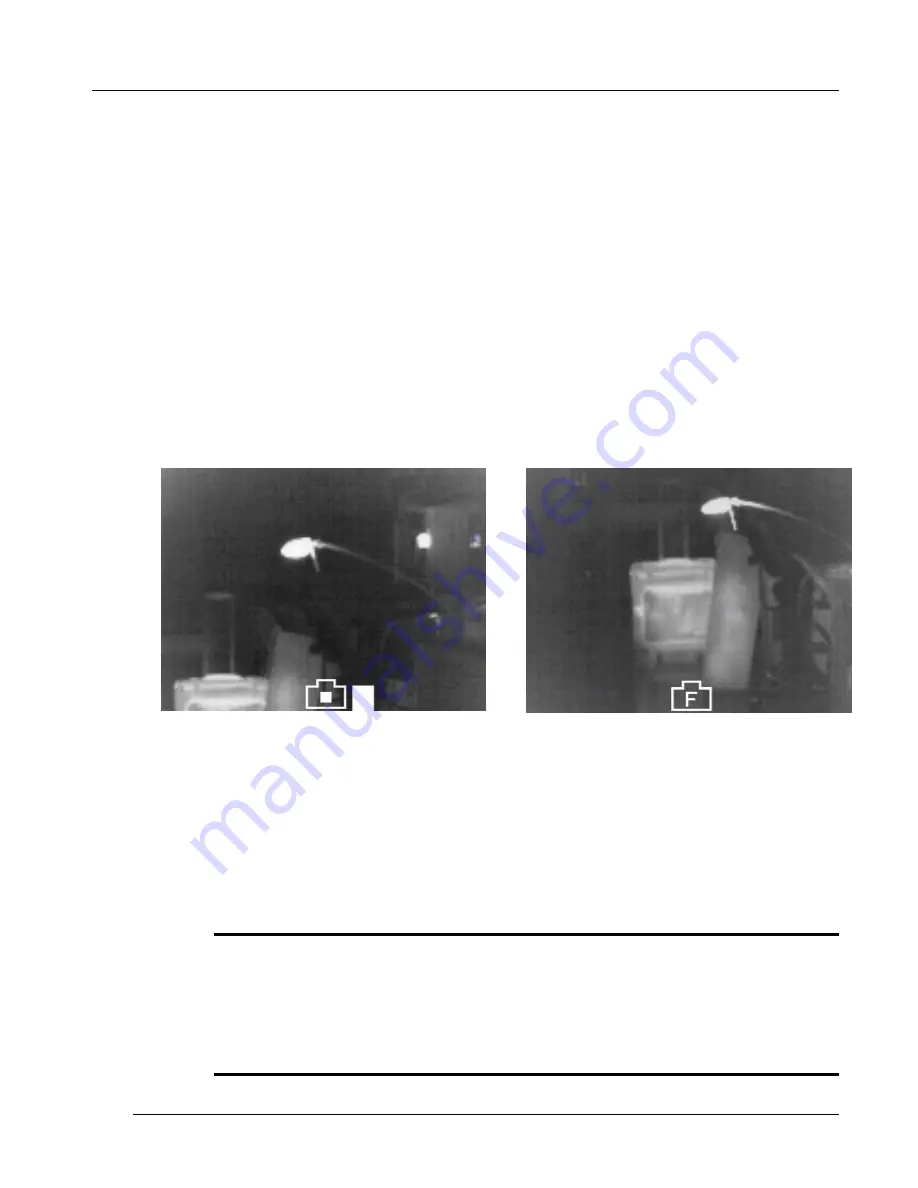
Figure 10: FlashSight image-capture icon 
and capacity gauge. 


Figure 11: FlashSight 100% full icon.


To delete the image memory, hold the image-capture button continuously for 
six seconds. The camera icon will begin blinking on the screen after the first 
three seconds (which gives the user time to abort image delete mode) and it 
will turn solid once the delete operation is initiated. When the icon turns solid, 
the image-capture button can be released. 
 

Note 

It is not possible to delete a single image – the entire image memory must be erased.  
It is recommended that the erase process be performed as a first step each time the 
sight is used so that the full memory is available. Images are NOT deleted during the 
download process. You must always use the delete process described above to 
clear image memory. 

Summary of Contents for FlashSight

Page 1: ...Copyright 2006 FLIR Systems Inc 431 0002 09 10 FlashSight User s Guide INDIGO OPERATIONS...

Page 2: ...ut permission and shall not be duplicated used or disclosed in whole or in part except to the extent provided in any contract of which this document is made a part This restriction does not limit the...

Page 3: ...ormation 5 4 FlashSight User Controls 7 4 1 On Off Button 7 4 2 Shutter Button 8 4 3 Image Capture Button 9 4 4 Menu Control 10 4 5 Eyepiece Focus 12 4 6 Lens Focus 12 5 FlashSight Image Download 12 6...

Page 4: ...re range 40 o C to 55 o C Not all AA batteries are specified over this same temperature span Check the manufacturer s specifications of your selected battery to verify the valid temperature range For...

Page 5: ...jective lens When the lens cap is not in place avoid pointing the sight directly at extremely high intensity radiation sources such as the sun lasers arc welders etc This warning applies whether or no...

Page 6: ...as a handheld device The heart of the FlashSight assembly is Indigo Systems Micron Omega core the world s smallest lightest lowest powered infrared imager Two lens options are available 30 mm 13 9 x 9...

Page 7: ...FlashSight User s Guide Copyright 2006 FLIR Systems Inc 431 0002 09 10 Version 100 4 Figure 1 FlashSight Deluxe Kit...

Page 8: ...eyecup to your eye pressing slightly against your face to open the eyecup flaps Adjust the eyepiece focus by rotating the eyepiece as shown in Figure 6 If necessary also adjust the focus of the lens a...

Page 9: ...09 10 Version 100 6 Figure 2 Installing batteries in the battery case Figure 3 Installing the battery case into FlashSight Figure 4 Turning on FlashSight Figure 5 Opening the lens cap Figure 6 Adjusti...

Page 10: ...ure 8 FlashSight User Controls 4 1 On Off Button The on off button is located on the left side of the FlashSight assembly To turn the system on simply press the button then release To prevent inadvert...

Page 11: ...l the shutter operation is completed While it is recommended to leave FlashSight in its automatic shutter mode whenever possible there are certain circumstances that call for a disabled shutter One of...

Page 12: ...hen the gauge reaches 100 a memory full icon will appear when you attempt to capture another frame which indicates no more images can be stored without first deleting the full contents of memory The m...

Page 13: ...is a push turn device i e it can be rotated like a knob and also pushed like a button Pressing the button will cause an on screen menu as shown in Figure 12 to be displayed Each row of the menu allow...

Page 14: ...rast to be adjusted Note The cursor will skip over the third row when the sight is in automatic video optimization mode In this mode brightness and contrast settings are updated automatically To adjus...

Page 15: ...on the focus adjustment of the lens The seal on the eyepiece can be tight so it may be necessary to squeeze the base firmly to adjust focus 4 6 Lens Focus The camera lens is focused by rotating the le...

Page 16: ...mm 8 3 x 6 3 Eyepiece eye relief 25 mm 1 inch Temporal NEdT Configuration Sensitivity NEdT 30 mm f 1 6 85 mK 50 mm f 2 0 85 mK Turn on time Time Degrees 4 seconds above 10 C 14 F 30 seconds at 32 C 2...

Page 17: ...e subject to change without notice See the FlashSight Product Specification ISC doc 431 0001 01 09 for detailed requirements 7 FlashSight Interfaces RS170A NTSC compatible output 75 ohm load impedance...

Page 18: ...tissue onto the lens surface and then drag the tissue across the lens surface Repeat several times with different pieces of tissue 2 Repeat the same step using IPA instead of water Drag the final piec...

Page 19: ...the objective of finding a single material that would give the desired reduction in brightness as well as the maximum reduction in heat He began the experiment by actually repeating Newton s prism ex...

Page 20: ...ably be doomed to the use of reflective elements exclusively i e plane and curved mirrors Fortunately this proved to be true only until 1830 when the Italian investigator Melloni made his great discov...

Page 21: ...y patents were issued for devices to detect personnel artillery aircraft ships and even icebergs The first operating systems in the modern sense began to be developed during the 1914 18 war when both...

Page 22: ...military infrared research programs into the possibilities of developing passive no search beam systems around the extremely sensitive photon detector During this period military secrecy regulations c...

Reviews: