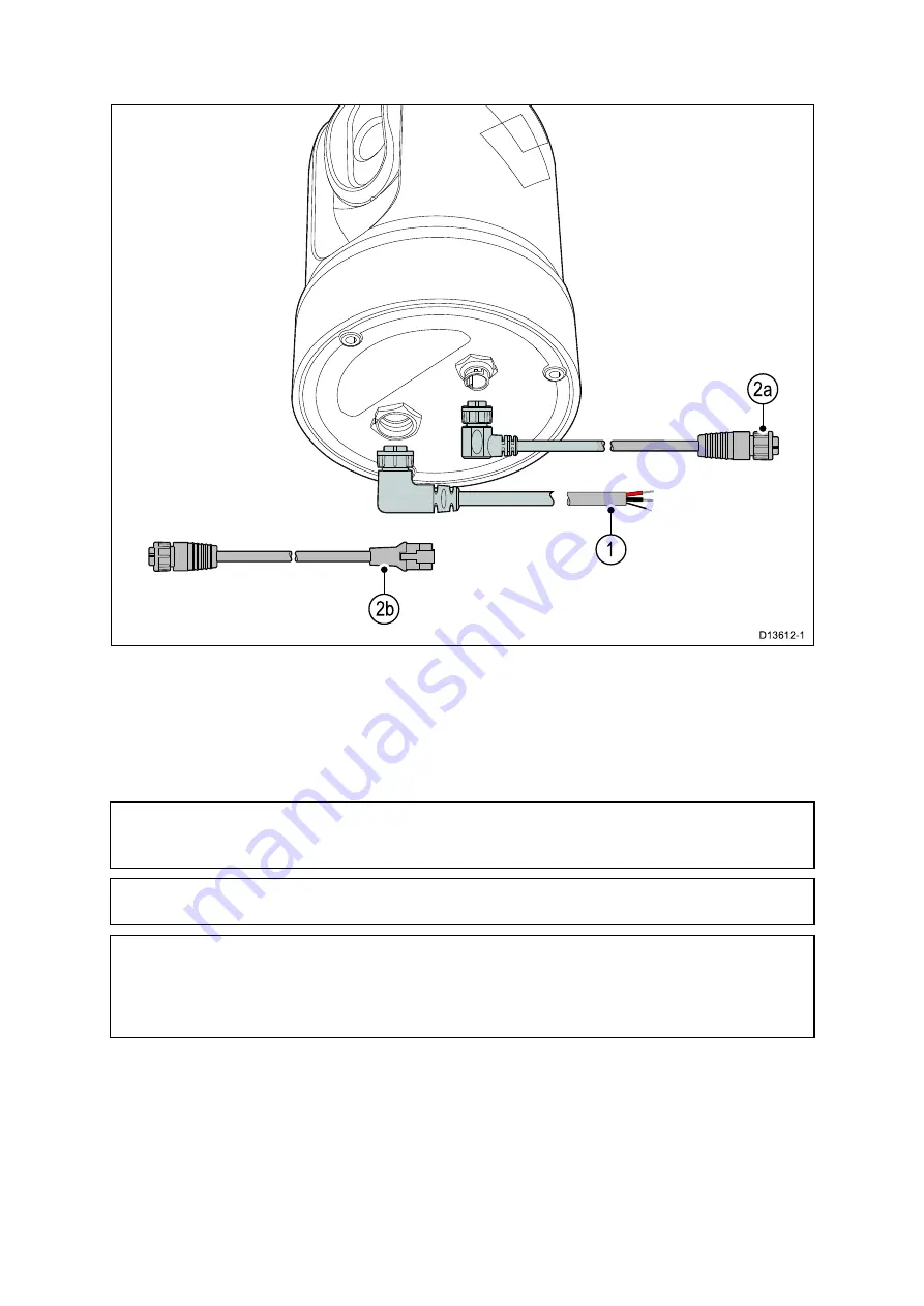
4.2 Connections overview
1.
Power and drain
2.
RayNet connection to:
a.
RayNet connector on Raymarine network switch or LightHouse™-powered
Raymarine multifunction display (using RayNet-to-RayNet cable), OR
b.
RJ45 connector on third-party network switch, PC/laptop computer, or IP video
decoder (available separately), using the supplied RayNet-to-RJ45 adapter cable.
Note:
The supplied right-angled RayNet and Power cables are suitable for mounting on
surfaces up to 25.4 mm (1.0 inch) thick. When mounting on thicker surfaces, you may
need to use RayNet and Power cables with straight connectors (available separately).
Note:
The cables should be routed to a dry area of the vessel for connection.
Alternatively you must ensure that all connections are water tight.
Note:
If you want to make cable connections to the camera before mounting it to
your vessel (for example, to test the camera), first attach the three threaded studs to
the base (see
). This will help to protect the cable connectors
on the base of the camera, and also provides a stable platform, helping to prevent
damage caused by the unit rolling off the edge of the work surface.
Connecting cables
Follow the steps below to connect the cable(s) to your product.
1. Ensure that the vessel's power supply is switched off.
2. Ensure that the device being connected has been installed in accordance with the
installation instructions supplied with that device.
3. Ensuring correct orientation, push cable connectors fully onto the corresponding
connectors.
4. If applicable, engage any locking mechanism to ensure a secure connection.
38
Summary of Contents for E70353
Page 2: ......
Page 4: ......
Page 8: ...8 ...
Page 14: ...14 ...
Page 31: ...3 9 Product dimensions M100 M200 Series Planning the installation 31 ...
Page 34: ...34 ...
Page 48: ...Multi camera system with video monitor two Raymarine MFDs two JCUs and a web browser 48 ...
Page 50: ...50 ...
Page 80: ...80 ...
Page 84: ...84 ...
Page 92: ...92 ...
Page 101: ......
Page 103: ......


