


Printed in Canada
June 14, 2007
Section 2 - Hydraulic Fan Group
01523r7.wpd
Page 2-9
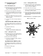
D.
Once fan starts reversing pitch, time a full pitch
reversal, it should not be less than
1 sec.
.
If the cycle is too long, drill out the orifice. If the cycle
is too short a smaller orifice is required. Contact your
local hydraulics supplier or Flexxaire
®
for orifice.
E.
Toggle the Air Flow Switch to change air flow to
the desired direction. Ie.: sets whether the fan acts
as a sucker or blower.
F.
Check the Purge button. This button when pressed
temporarily turns off the timer and when released
the timer starts up and does a purge for the
duration set on the “ON TIME”.
G.
Set the Timer by adjusting the “ON TIME”
(Duration) and the “OFF TIME” (Interval) to the
desired lengths. Select a duration and interval that
meets the application requirements . If unsure, set
“ON TIME” to 15 seconds and “OFF TIME” to 20
minutes.
NOTE 1:
“ON TIME” is the length of the purge
cycle (duration) and is adjustable
between 1-100 seconds. “OFF TIME”
is the time between purge cycles
(interval) is adjustable between 1-100
minutes.
NOTE 2:
This Timer gives the option of setting
interval times as low as 1 minute, but
it is not recommended to set intervals
below 5 minutes due to reduction in
cooling capacity and potentially
excessive wear of fan components.
H. Step only applicable for 3-Position control kit.
Remove jumper from temperature switch leads and
the fan should return to NEUTRAL pitch if engine
is cold.
NOTE:
The return to NEUTRAL pitch is
accomplished due to the centrifugal forces
from the spinning blades. At low idle, it
may take longer to return to NEUTRAL
pitch as the forces are not as great as at
high idle.
I.
Step only applicable for 3-Position control kit.
Warm up engine until the fan goes into pitch.
Ensure the engine temperature is not too high. If
engine gets too hot before fan goes into pitch; the
temperature switch is installed in a cold spot on the
engine block and a location closer to the
thermostat is required. If this is the only location for
the temperature switch then a switch with a lower
temperature rating is required. Contact your local
dealer or Flexxaire
®
.
NOTE:
By adding a jumper to the temperature
switch leads, the valve essentially
becomes a 2-Position valve with full
“PULL” or full “PUSH” and no NEUTRAL
position. Do this until the correct switch is
obtained.
2.2.2.7. FX Fan Operation
2-Position Valve Kit
The 2-Position Solenoid Valve setup places the
fan into pitch in standard operating direction on
start up of machine. Purges occur at the preset
intervals for the preset duration. The manual purge
switch may be pressed at any time to initiate a
purge cycle. When the purge switch is pressed
and released, the fan will do a full purge cycle and
the timer will be reset. The next purge will happen
at the full interval from when the button was last
pressed. The air flow toggle switch may be used at
any time to reverse the pitch.
3-Position Valve Kit
The 3-Position Solenoid Valve setup puts the fan
into “NEUTRAL” pitch until engine temperature is
high enough to make the temperature switch
close. The fan will then go into full pitch in the
standard operating direction. If the engine
temperature drops (approximately 8
?
F), the
temperature switch will open and the fan will go
back to neutral pitch. Purges will occur at the
preset intervals when the fan is in full pitch (if the
fan is in neutral pitch, purges will not occur). The
manual purge button may be pressed at any time
to initiate a purge cycle. When the purge switch is
pressed and released, the fan will do a full purge
cycle and the timer will be reset. The next purge
will happen at the full interval from when the
button was last pressed. The air flow toggle switch
may be used at any time to reverse the pitch.
NOTE 1:
The Temperature switch disables the
solenoids when it is open (cold). This
prevents any purging: automatic or
manual. As well the toggle switch will
not reverse the pitch while the fan is
in neutral.
NOTE 2:
If multiple temperature switches are
used, then the fan will go to neutral
pitch when ALL switches are open. If
any switch is closed, the fan will go to
full pitch.
Summary of Contents for FX 2000 Series
Page 2: ...Page 0 2 01523r7 wpd Hydraulic Manual June 14 2007 Printed in Canada...
Page 4: ...Page 0 4 01523r7 wpd Hydraulic Manual June 14 2007 Printed in Canada...
Page 6: ...Page 1 2 01523r7 wpd Section 1 General Information Overview June 14 2007 Printed in Canada...
Page 10: ...Page 2 2 01523r7 wpd Section 2 Hydraulic Fan Group June 14 2007 Printed in Canada...


