


Printed in Canada
June 14, 2007
Section 2 - Hydraulic Fan Group
01523r7.wpd
Page 2-3
2.1. INTRODUCTION
This manual explains Flexxaire
®
’s FX series of fan
systems. The FX fan blade pitch is controlled
hydraulically through two hydraulic ports. These ports
supply fluid to a small double acting hydraulic cylinder
embedded within the mainshaft. Pressuring either
hydraulic port will move the fan blades into “PUSH” or
“PULL” positions, respectively.
2.1.1
.
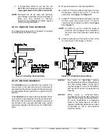
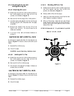
External Identifiable Components
The Hydraulic Fan Assembly can be identified by
several external major components in
Figure 1
. Use
this diagram for terminology and component
identification.
2.1.2. Blades
Typical service life for fan blades is 10,000 hours and
higher. Actual blade life is dependent on operating
conditions. High abrasive environments will subject
the blades to higher wear.
Figure 1, External Fan Assembly
96229r0
1. Hub Assembly
4. Hydraulic Connector
2. Blade Assembly
5. Fan Mounting Bracket
3. Pulley
6. Mainshaft Assembly*
*Serial number and Fan part number stamped on mainshaft.
Summary of Contents for FX 2000 Series
Page 2: ...Page 0 2 01523r7 wpd Hydraulic Manual June 14 2007 Printed in Canada...
Page 4: ...Page 0 4 01523r7 wpd Hydraulic Manual June 14 2007 Printed in Canada...
Page 6: ...Page 1 2 01523r7 wpd Section 1 General Information Overview June 14 2007 Printed in Canada...
Page 10: ...Page 2 2 01523r7 wpd Section 2 Hydraulic Fan Group June 14 2007 Printed in Canada...


