


Page 2-6
01523r7.wpd
Section 2 - Hydraulic Fan Group
June 14, 2007
Printed in Canada
2.2.2.1. Hydraulic Specifications
Flexxaire
®
FX Fan assemblies are shipped with #4
ORB fittings with JIC (7/16" - 20 MALE 37
?
Flare end)
ends. The specifications below are required for the FX
fan system to operate.
Pressure Specification:
Flexxaire
®
fan requires a
source that operates between 300 and 1200 psi..
Operating pressures outside this range require
verification and acceptance from Flexxaire
®
Engineering.
Oil Specification:
The hydraulic seals used are very
compatible with most petroleum based hydraulic
and lubricating oils. Do not use high temperature
oils, aromatic solvents or industrial phosphate
esters; use of these fluids will require seal
replacement.
Interval Of Pitch Change:
The Flexxaire
®
fan should
be operated at a pitch change rate of not less then
1 sec.
.
Ie.: To go from full “PULL” to full “PUSH” (or
vise versa) positions must not be less then
1 second. An orifice in the hydraulic return
line is necessary to meet this requirement.
2.2.2.2. Selecting A Hydraulic Source
The Flexxaire
®
FX fan requires a hydraulic pressure
source from the machine. The source for your specific
application may be specified in the
Special
Instructions
under the title of “Recommended
Hydraulic Source” within the front cover page of this
manual. If not, there are several considerations:
A.
The fan uses a small hydraulic piston with a 1"
stroke. There is no “leakage” in the fan and it takes
very little flow to adjust the blade pitch (a couple
cubic inches (in³) of oil); thus, the fan puts very
little demand on a hydraulic system, and will not
affect most systems.
B.
The hydraulic source must have an acceptable
operating pressure.
C.
The hydraulic source must maintain the minimum
operating pressure to hold the fan blades in pitch.
NOTE:
The Differential Pressure (Source Pressure
minus Return Pressure) must meet or exceed
the minimum pressure requirement.
D.
Avoid hydraulic systems with high pressure spikes.
E.
The hydraulic source must have acceptable oil
types, refer to
Table 2, Page 2-10 - Approved
Oils and Service Properties
.
F.
Potential hydraulic sources/systems:
i.
Pilot / Charge pressure systems
ii.
Parking brake systems
iii.
Power steering systems
iv.
Final drive systems
v.
Any other hydraulic source that
meets the above specifications but
are not listed above may be a good
s o u r c e . C o n t a c t F l e x x a i r e
®
Engineering for verification.
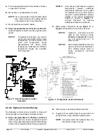
G.
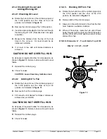
Once a suitable hydraulic source is selected. Find
locations to install “T” fittings in the pressure
(source) line and return tank line on this system.
2.2.2.3. Control Kit Information
After the fan is mounted onto the machine, the
hydraulic solenoid valve, hydraulic lines, etc. must be
installed. The Flexxaire
®
FX fan can be controlled with
a
2
or
3
position solenoid valve, or a full variable pitch
controller. Please contact Flexxaire
®
Manufacturing
Inc. for documentation on the full variable pitch
controller.
A
2 position
valve gives two pitch positions - full
“PUSH” and full “PULL”, and is suitable for
applications which
only
require purging.
A
3 position
valve gives three pitch positions - full
“PUSH”, full “PULL” and “NEUTRAL”. In NEUTRAL
pitch, the fan does not blow air and over cooling
problems can be reduced (as well as an increased
horsepower and fuel savings).
The control components are not supplied with the
Flexxaire
®
FX fan. Customers may purchase their
own components or purchase one of two control kits
which are available from Flexxaire
®
.
2-Position Control Kit -
P/N 12528
3-Position Control Kit -
P/N 12529
Flexxaire
®
control kits include the following
components:
i.
A Timer to automate purge cycles.
ii.
A Toggle Switch to set air flow direction for a
sucker or blower fan.
iii.
A Hydraulic Solenoid Valve, orifice and
fittings for the valve: to position fan blades.
iv.
A Momentary Switch to trigger manual purge
cycles.
Summary of Contents for FX 2000 Series
Page 2: ...Page 0 2 01523r7 wpd Hydraulic Manual June 14 2007 Printed in Canada...
Page 4: ...Page 0 4 01523r7 wpd Hydraulic Manual June 14 2007 Printed in Canada...
Page 6: ...Page 1 2 01523r7 wpd Section 1 General Information Overview June 14 2007 Printed in Canada...
Page 10: ...Page 2 2 01523r7 wpd Section 2 Hydraulic Fan Group June 14 2007 Printed in Canada...


